Lab: Switches
September 16, 2020
Physical ComputingIn this lab I learned about the various types of electrical switches and created a custom switch out of a coaster.
Making a Switch
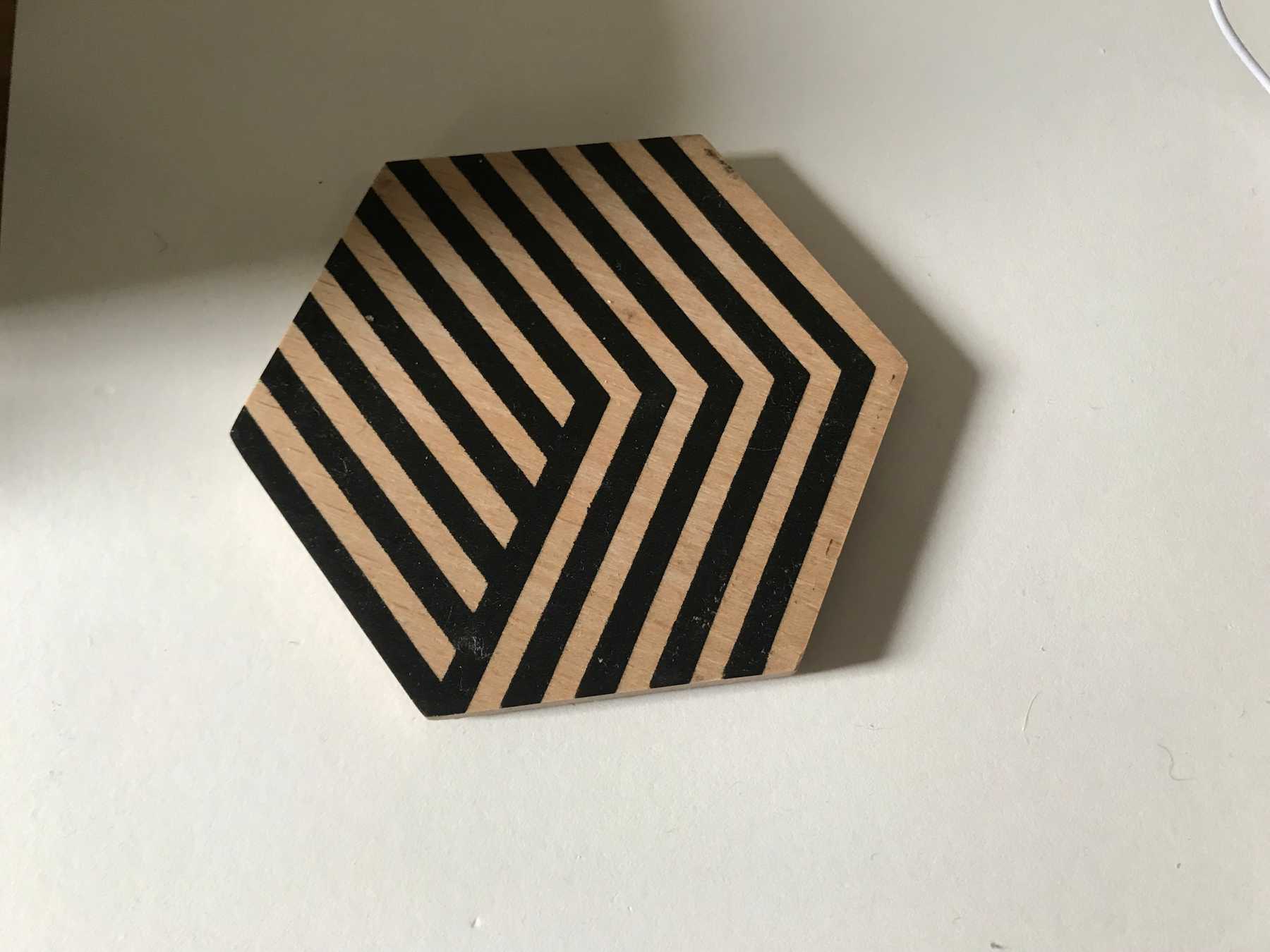
I decided to turn a coaster into an electrical switch, so that an LED turns on when a modified mug is placed on it.
The switch will be closed when the mug is on the coaster.
To make this happen I used aluminum foil as a conductor, taping a pad of foil to each side of the coaster.
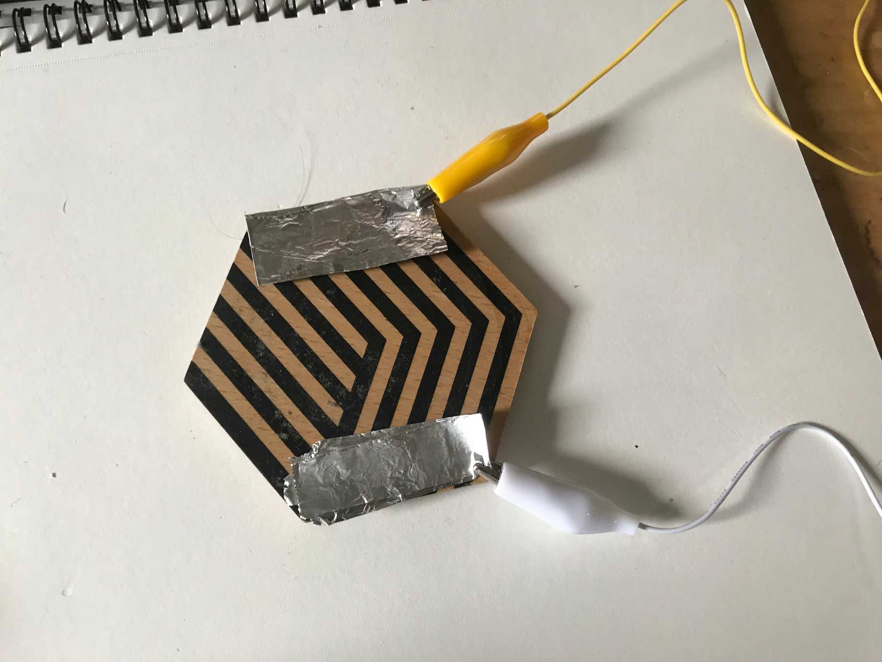 Two aluminum pads on either side of the coaster
Connecting to the foil using alligator clips, I measured for continuity. As expected, there was no continuity in the “unpressed” state.
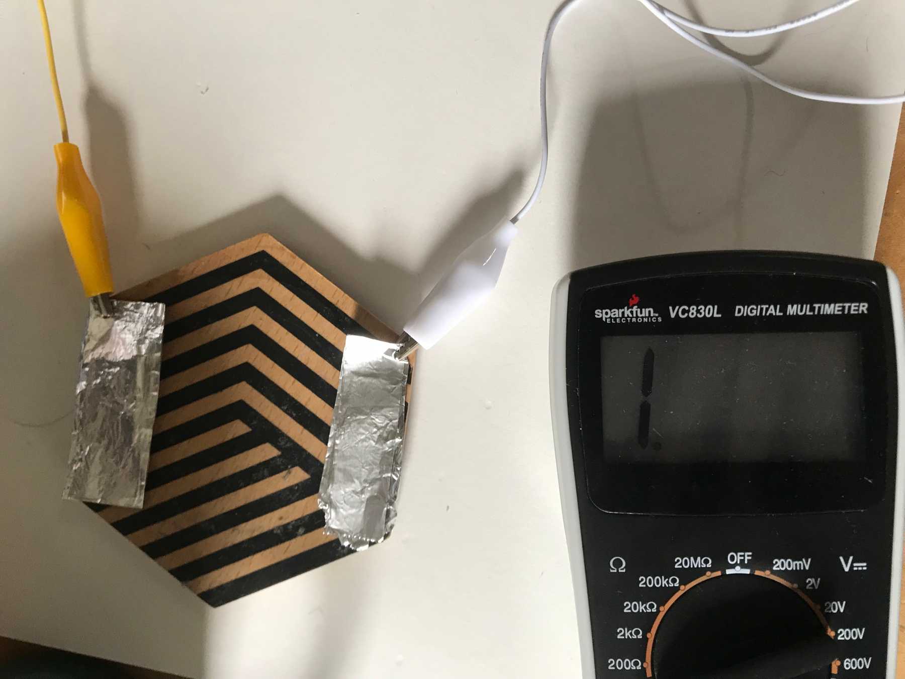 Measuring no continuity on the empty coaster
I then taped a strip of foil to the bottom of the mug.
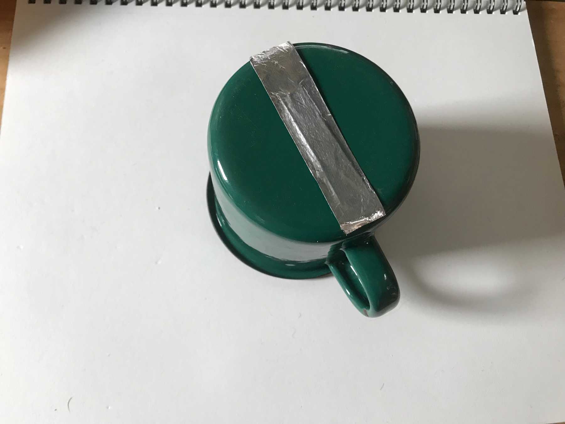 Aluminum foil taped to the bottom of the mug
The multimeter beeped when I placed the mug on the coaster - continuity!
The connection becomes continuous when the mug is placed on the coaster
Now I needed to wire the switch to my breadboard. I used the same schematic introduced in the electronics lab.
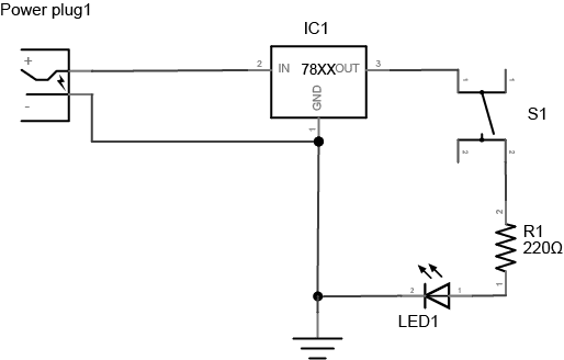 Schematic view showing a pushbutton in series with a 220Ω resistor and LED
I connected one side of my custom switch to Vin and the other side to the input of the 220Ω resistor, which is connected to the LED and then ground.
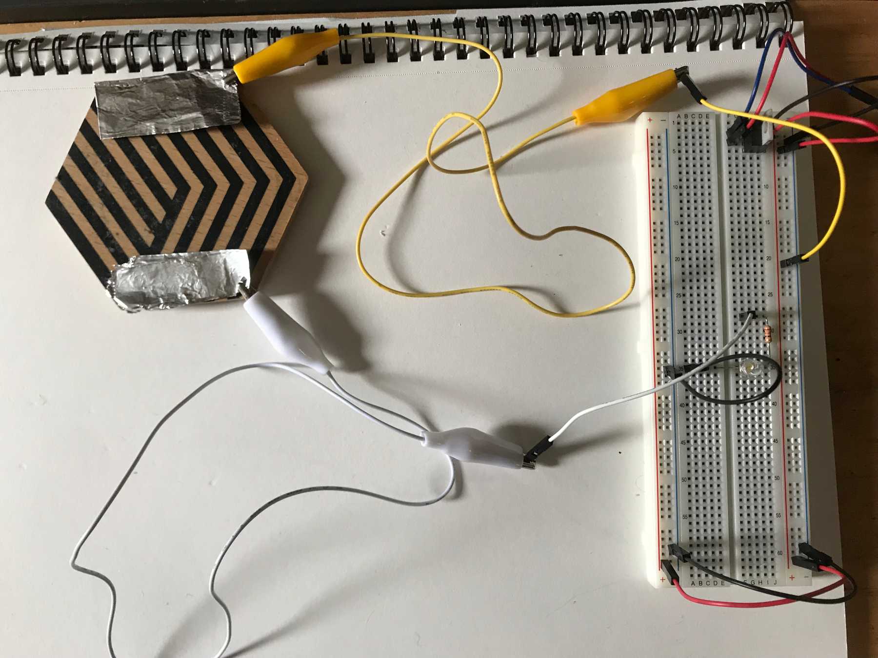 Wiring the coaster switch to the breadboard by connecting one side to Vin and the other to the resistor’s input
Placing the mug on the coaster closes the switch, illuminating the LED. Success!
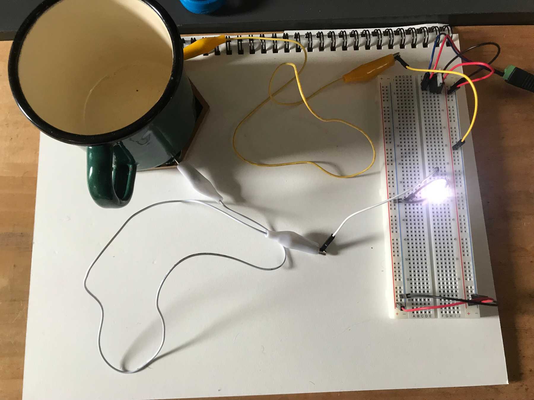 Placing the mug on the coaster closes the switch, illuminating the LED
It works!
One drawback to this design is that the mug must be placed at the correct rotation to close the switch. This could be avoided by creating a circular aluminum pattern on the bottom of the mug. That way the connection would occur no matter the mug’s orientation.
Other Switch Configurations
I also implemented two other switch configurations: switches in parallel and in series. With switches in parallel, pressing any one of them turns on the LED.
Switches in parallel: pressing any switch turns on the LED
With switches in series, you must press all of them to complete the circuit.
Switches in series: the LED can only be activated by pressing all three buttons
