Lab: Electronics
September 13, 2020
Physical ComputingIn this lab I will learn how to use the multimeter to measure continuity, resistance, voltage, and amperage.
Measuring Continuity
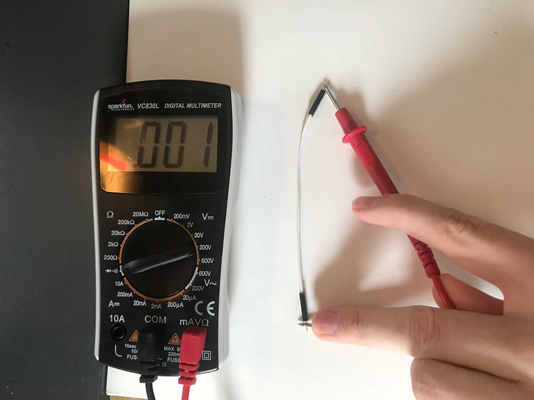
Continuity means that two points are electrically connected. I looked for continuity in a wires, a switch, the breadboard, and my hand.
Measuring a switch:
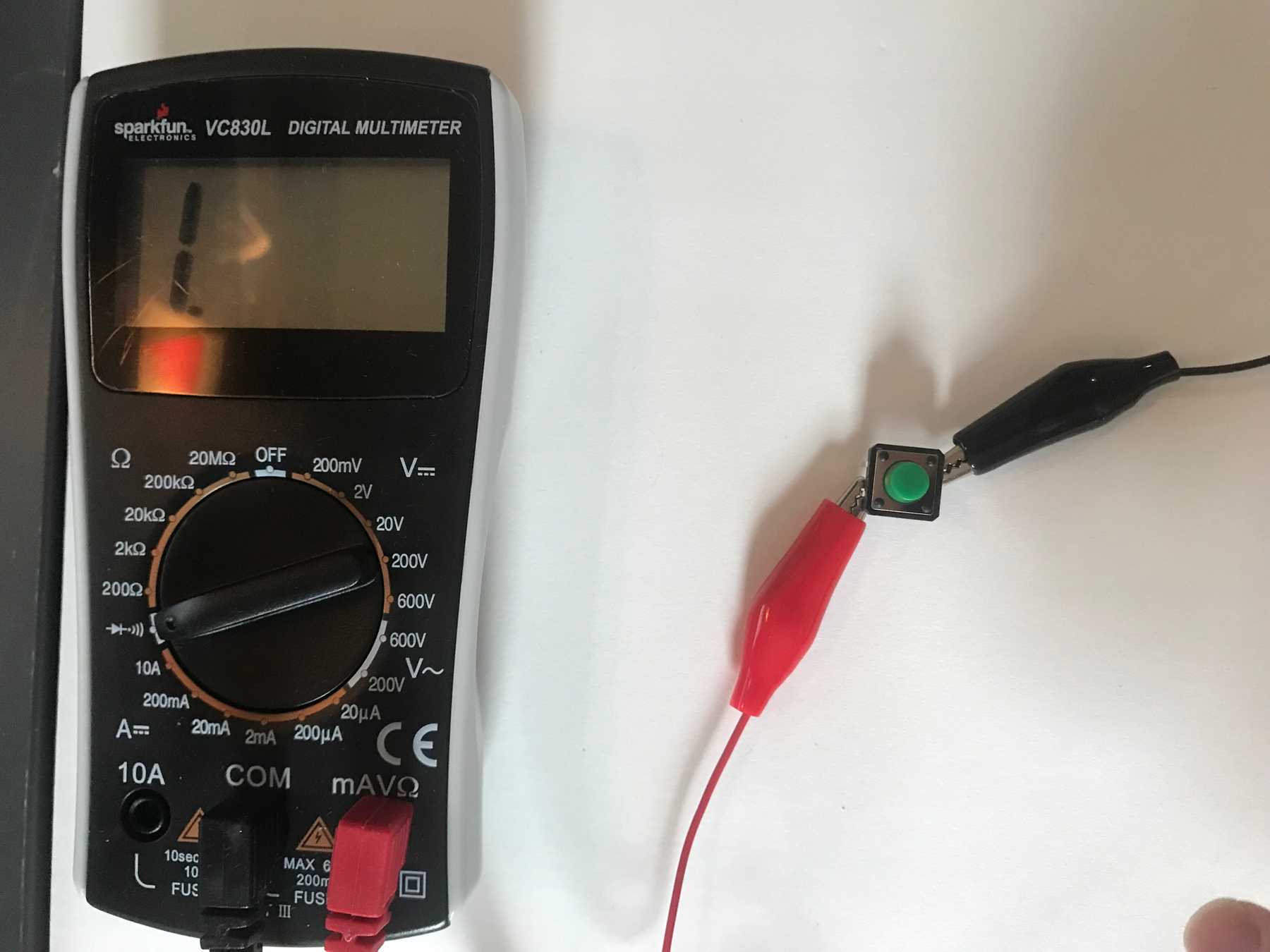 This switch is not continuous in it’s unpressed state
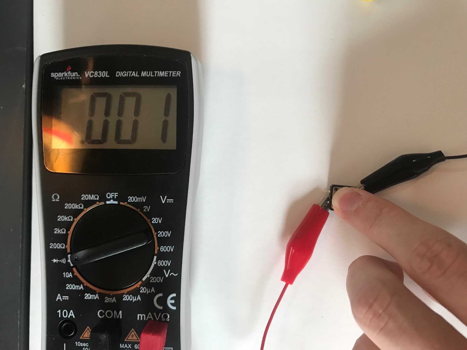 This switch is continuous when pressed
Measuring the breadboard:
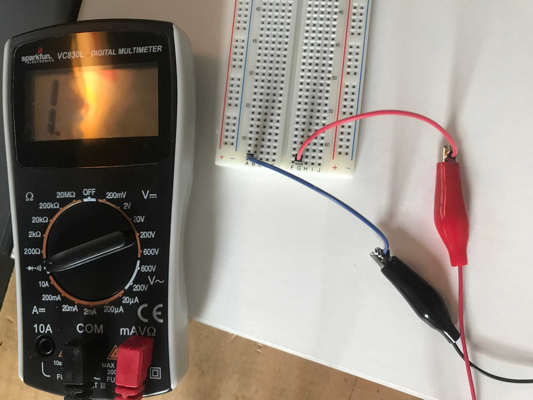 These two points are not continuous
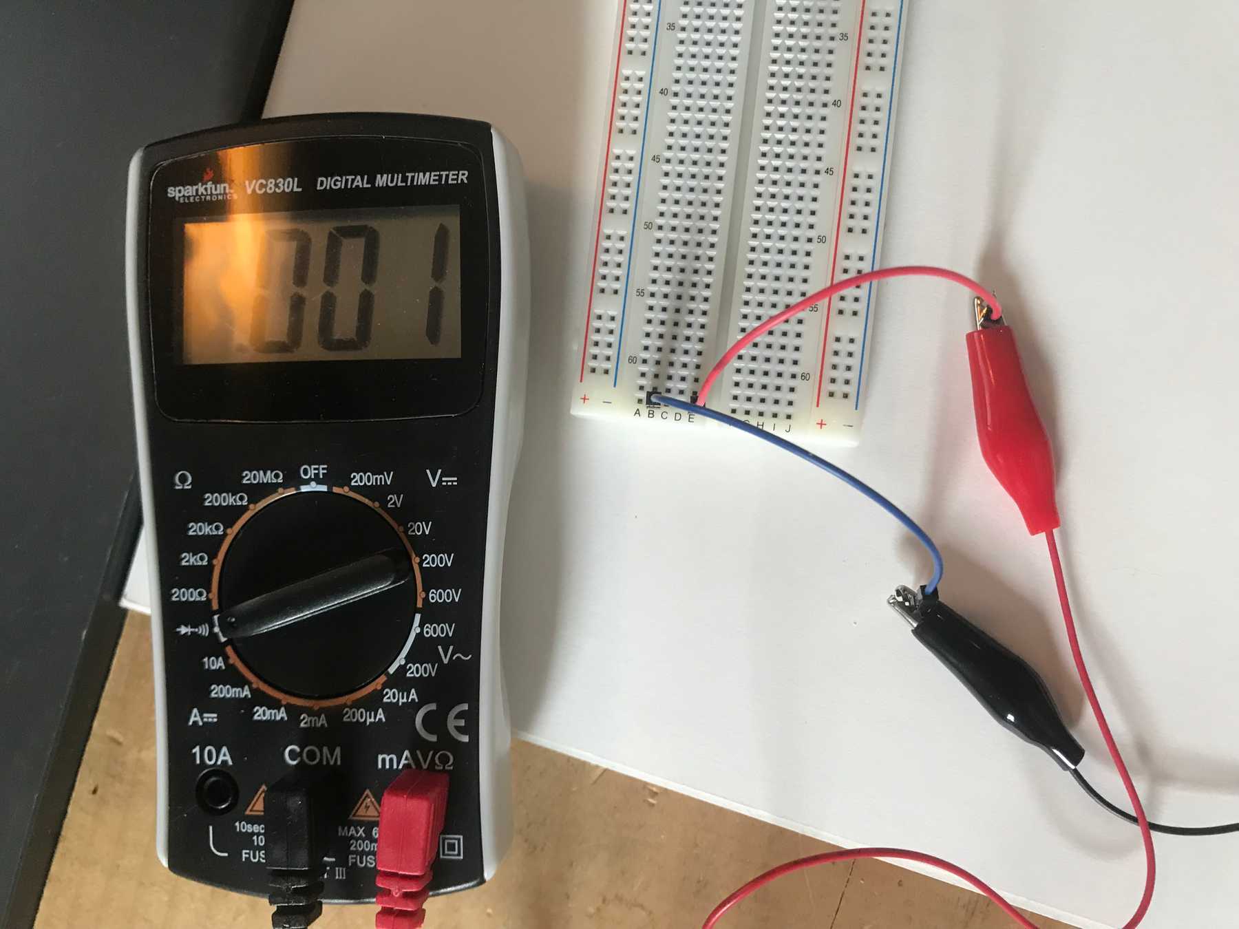 These two points are continuous
Measuring Resistance
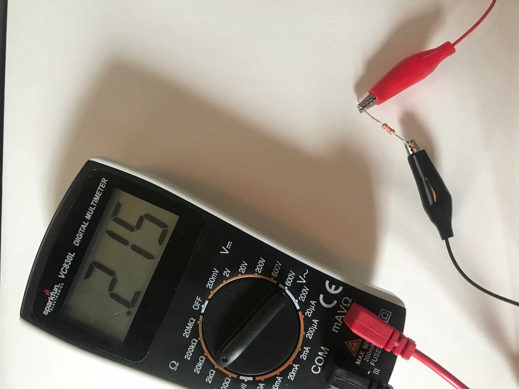
Resistance is the measurement of how much a certain path resists electrical current. This 220Ω resistor showed an actual resistance of 215Ω.
The resistance across my hand fluctuated around 5MΩ.
Measuring Voltage
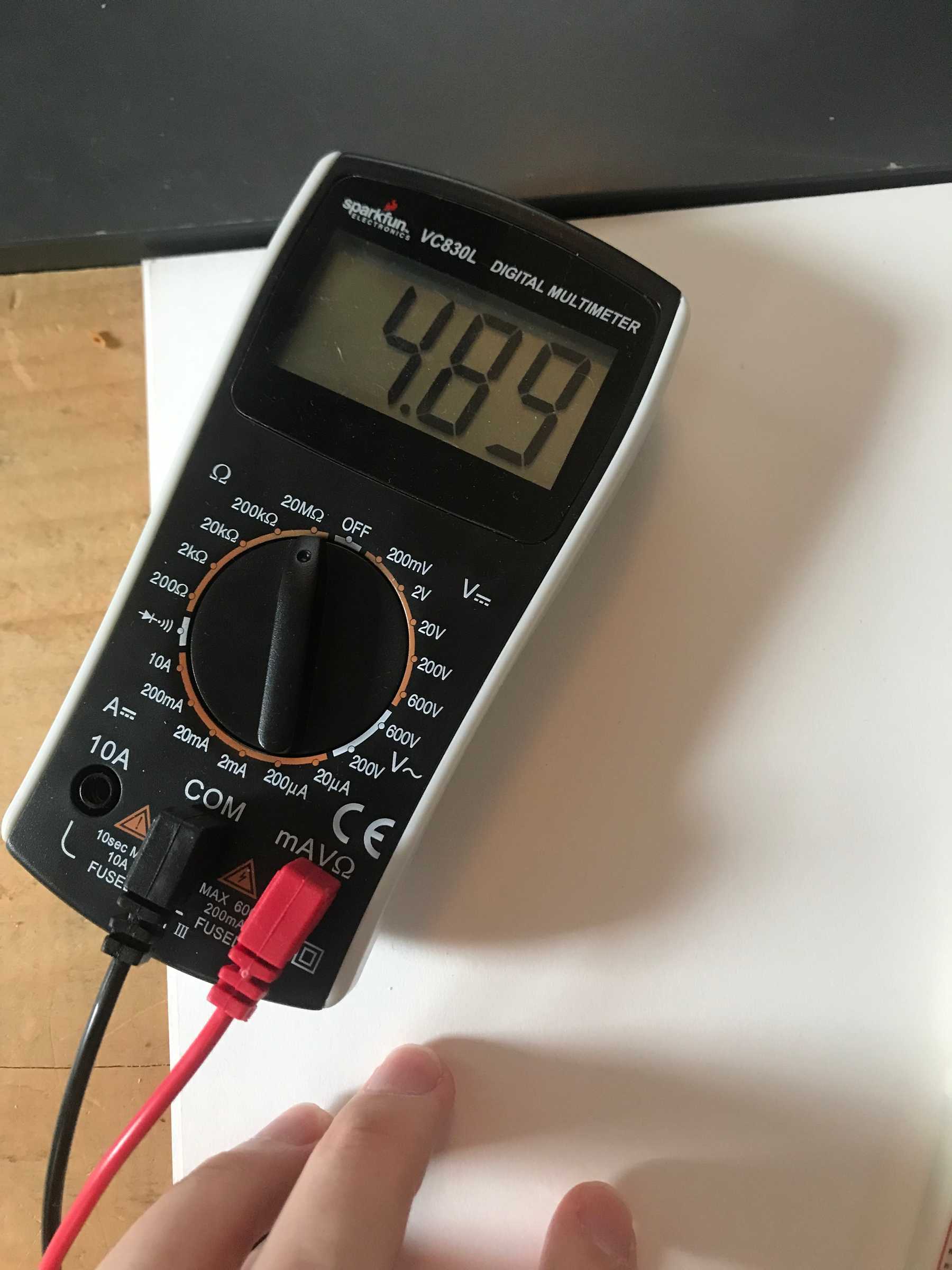
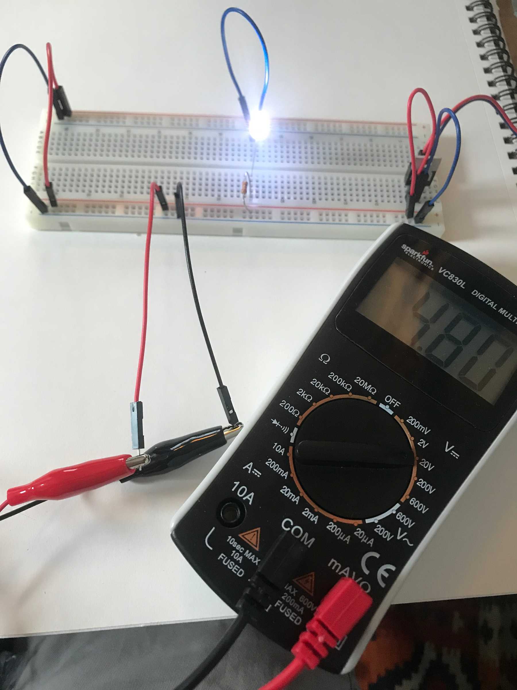
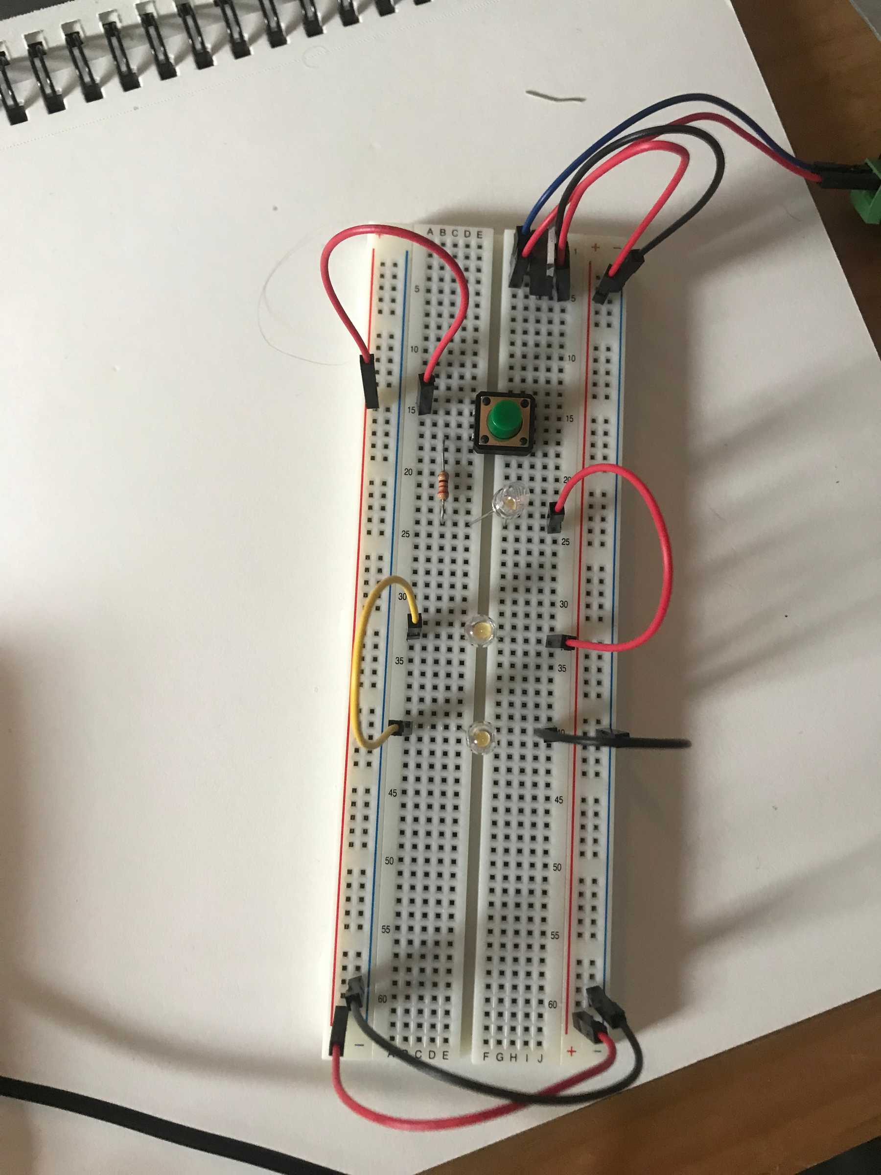
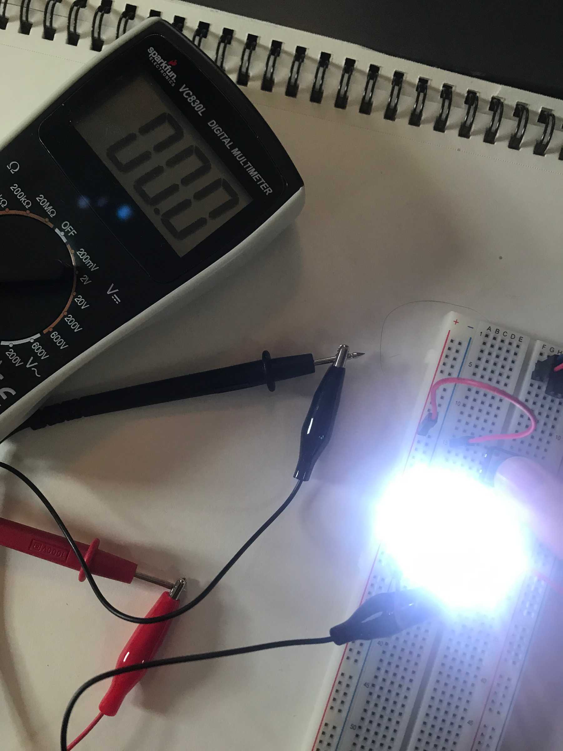
Voltage is a measurement of electrical potential between to points. To measure voltage I created this simple circuit: A 220Ω resistor in series with an LED. The voltage measured from power to ground is 4.80V.
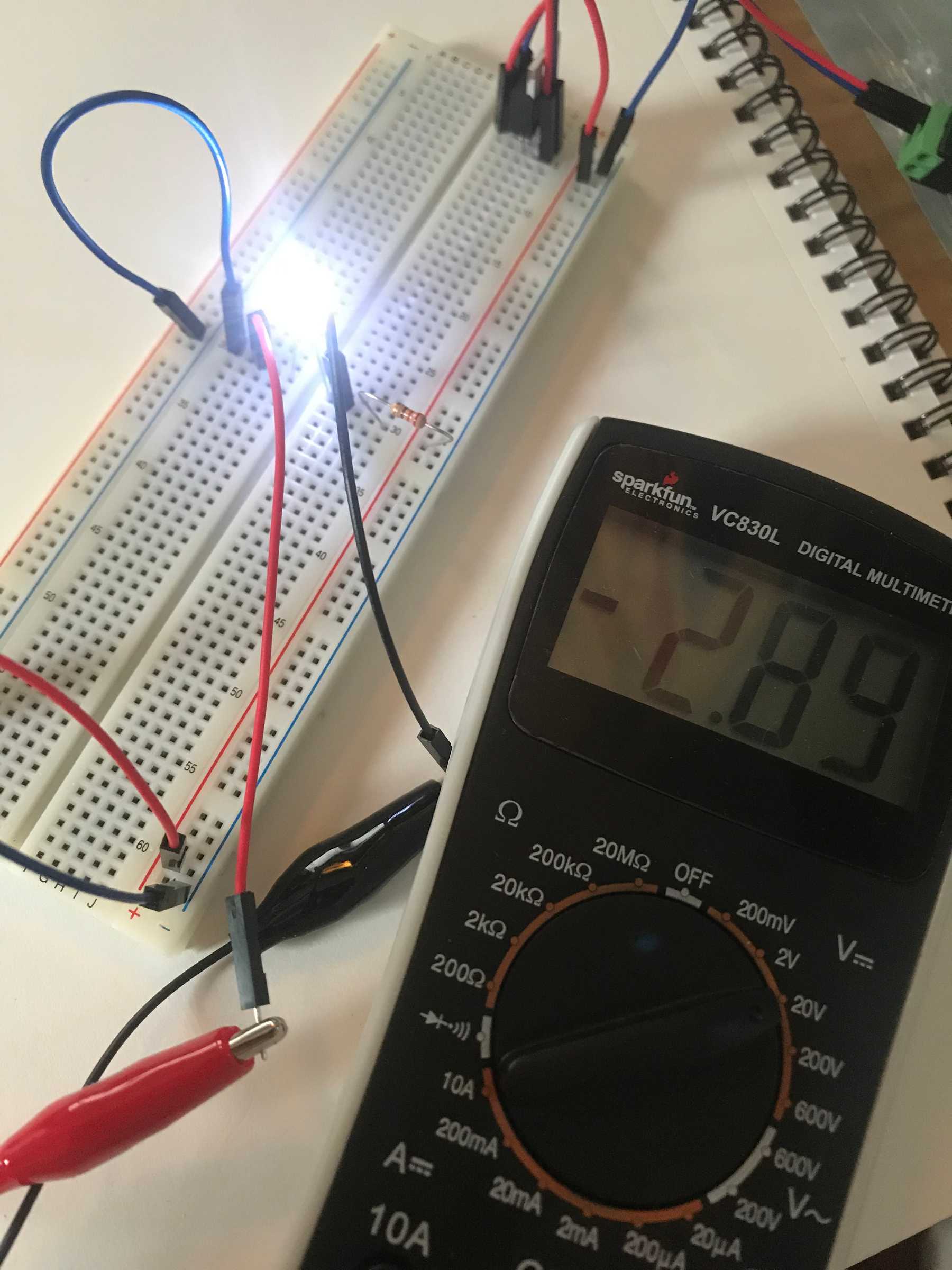
The voltage drop across the LED is 2.89V. I got a negative value because the black lead touches the point of higher voltage.
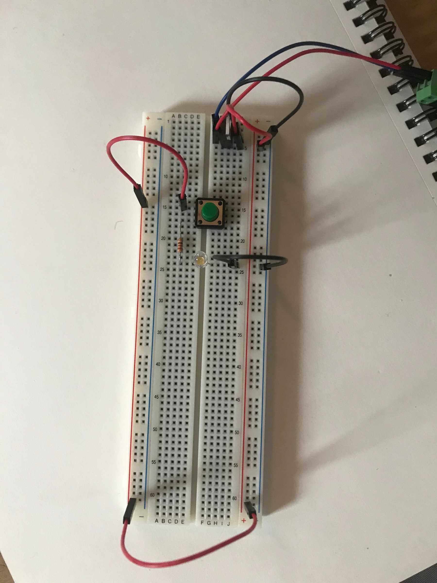
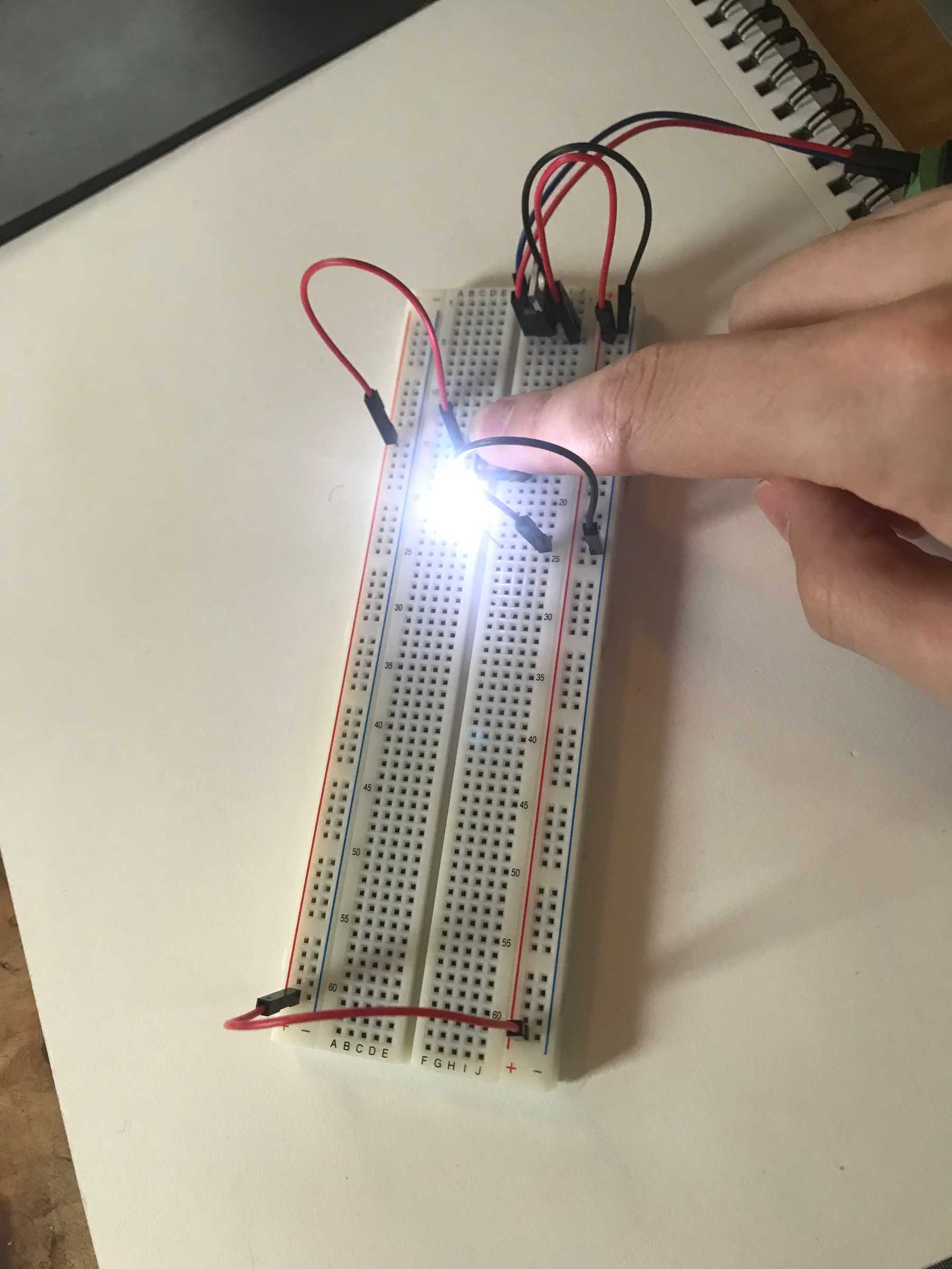
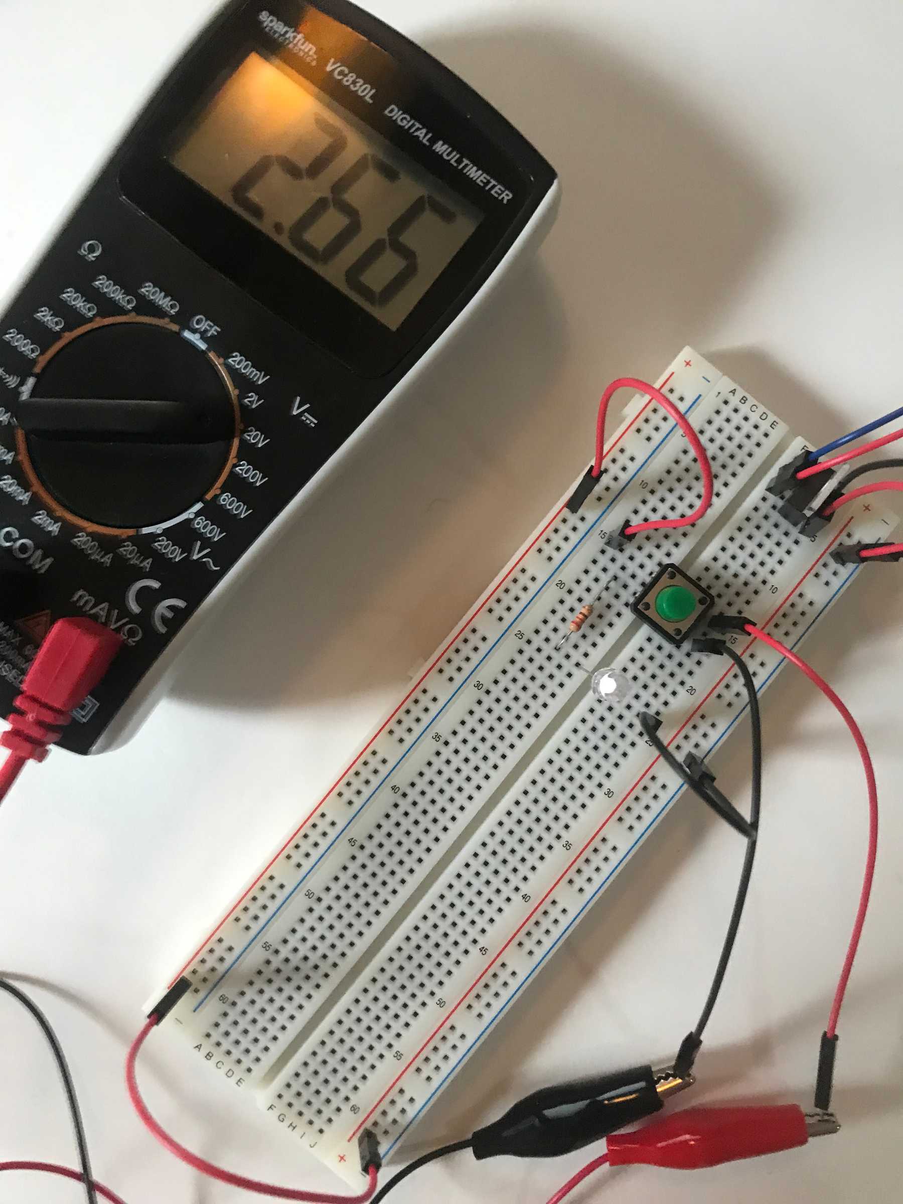
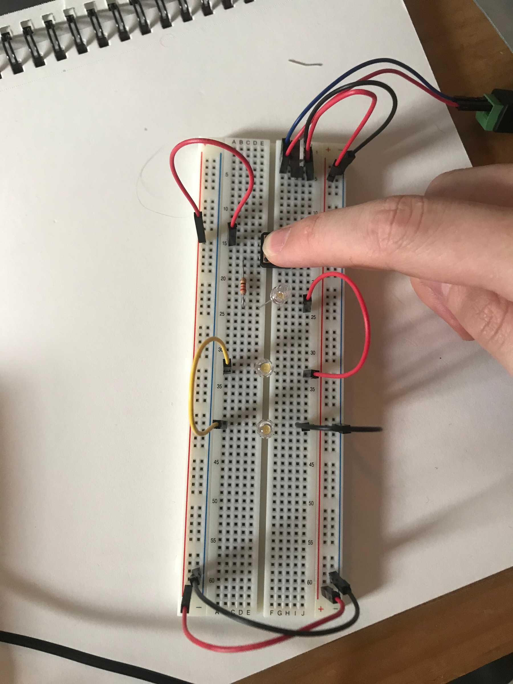
I then modified the circuit by adding a pushbutton in series before the resistor and LED.
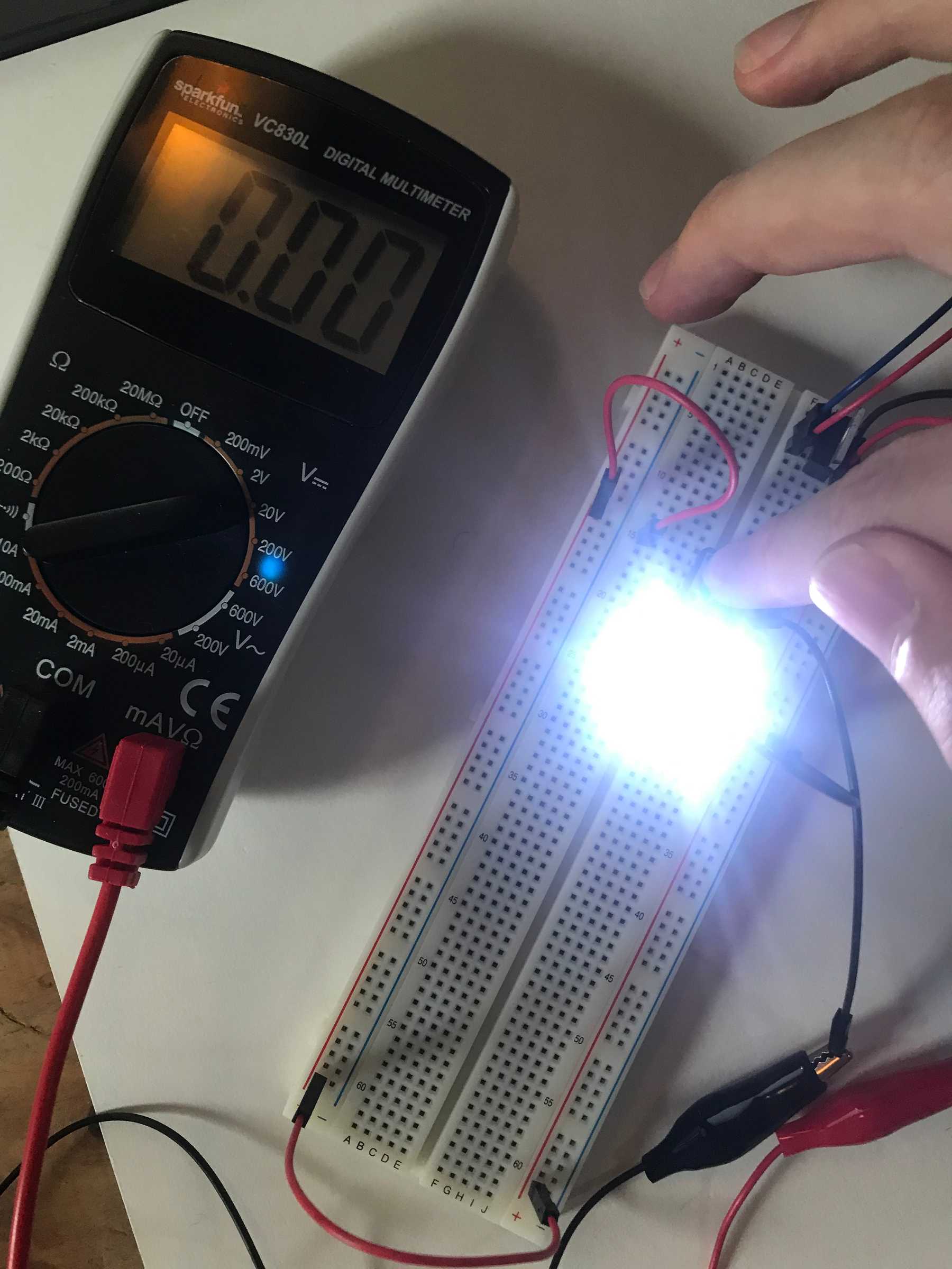
I measured the voltage drop across the pushbutton to be 2.66V when not pressed and 0V when pressed. This confused me a bit because I thought that the act of measuring the button’s voltage would bypass the button and complete the circuit. I noticed that the LED illuminated slightly which means that the circuit was indeed complete, but only a small voltage was reaching the LED.
When the button was pressed, the voltage drops across the resistor and LED were each 0V because the circuit was incomplete. When the button was pressed, the drop across the resistor was 2.15V and the voltage across the LED was 2.85. These add up to the 5V total voltage drop across the circuit.
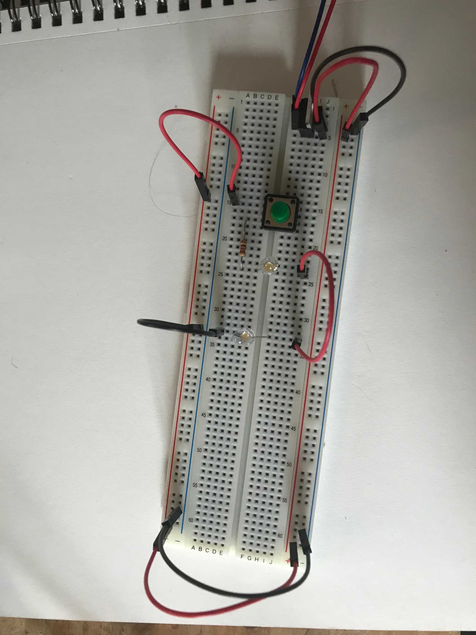
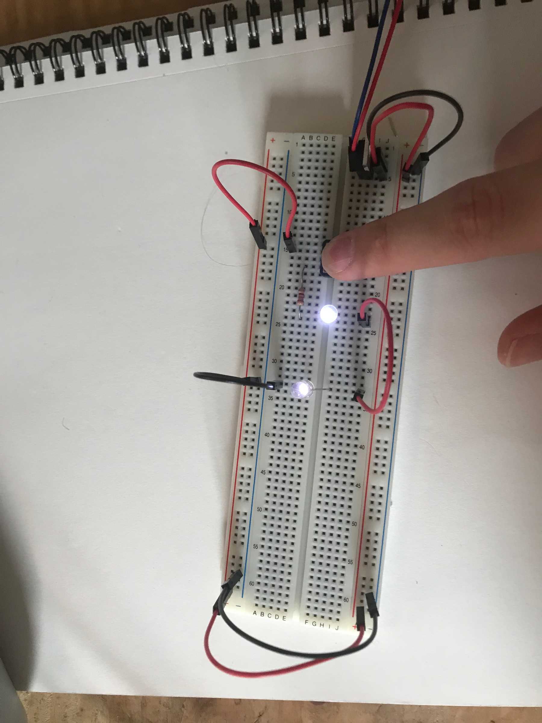
For the next circuit I added second LED in series with the first:
Pressing the button causes both LEDs to illuminate. The first consumed 2.46V and the second consumed 2.52V. The voltage across the resistor was just 0.01V because the LEDs were drawing the rest of the voltage. Added up, the voltage drop is 4.99V. The remaining 0.01V could be attributed to measurement fidelity or a slight loss of energy to light or heat.
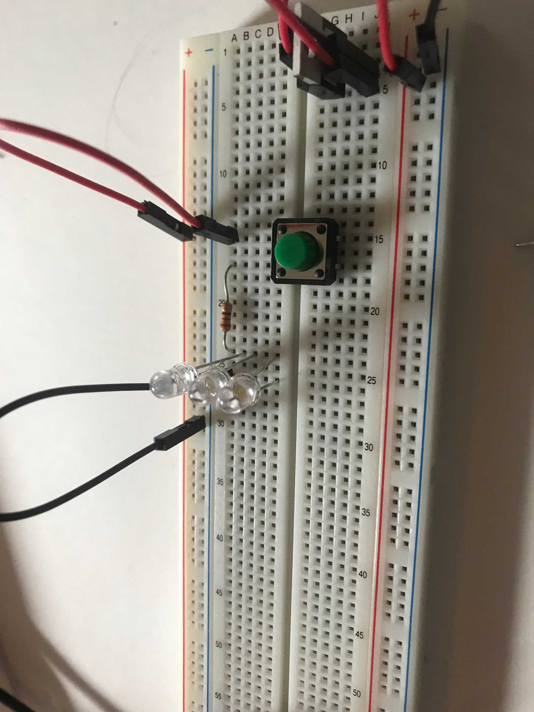
Adding a third LED in series with the other two causes none of the LEDs to light up when the button is pressed. This is because they each require about 2V, but the available power is only 5V. Because they are in series, each LED only receives about 1.67V.
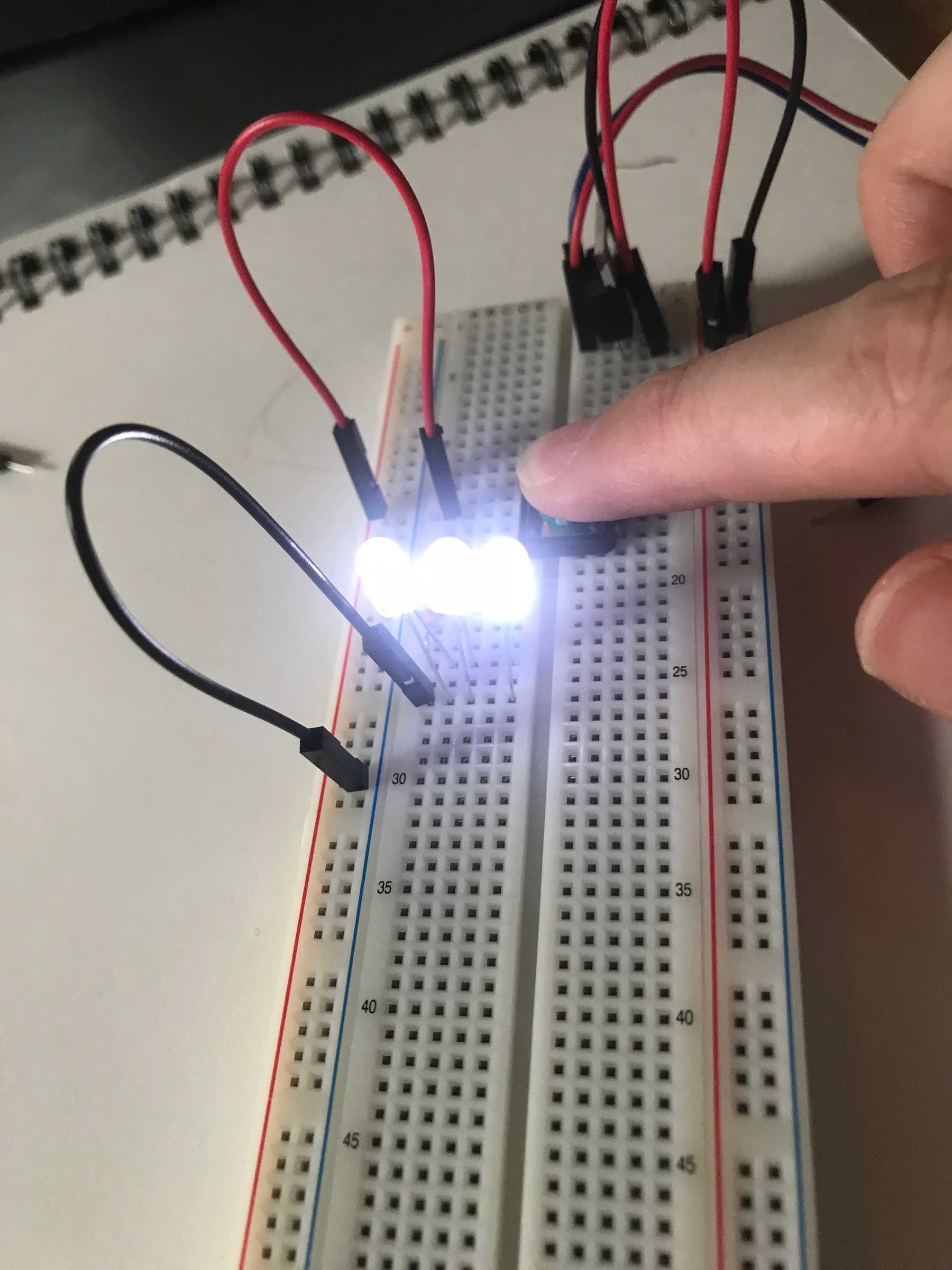
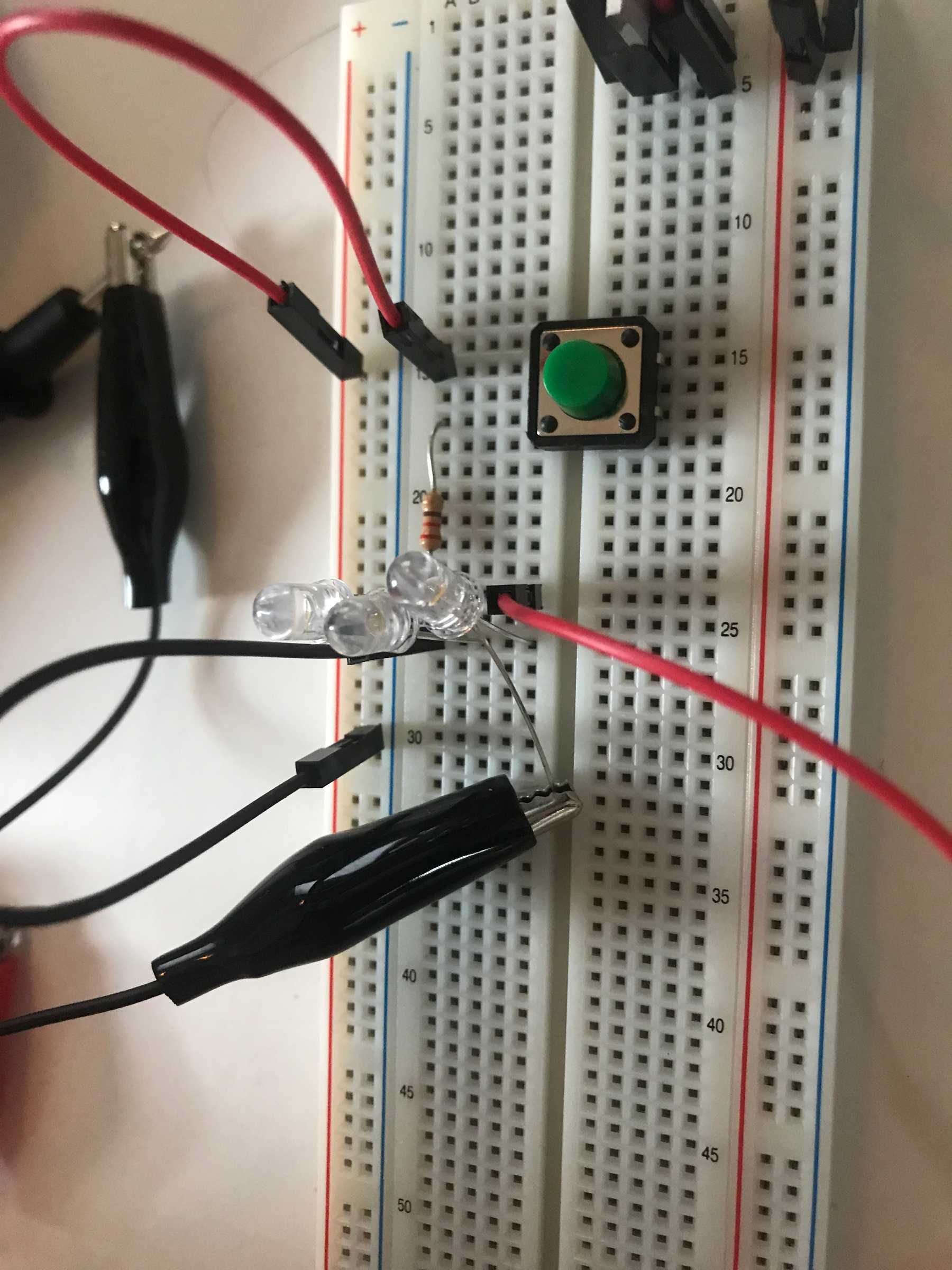
The next circuit orients the three LEDs in parallel:
The voltage drop across is the same across each LED: 2.72V, and 2.21V across the resistor. This works because the voltage is not divided across the three LEDs. sss
Measuring Amperage
Amperage is the unit of electrical current. I had trouble measuring the amperage across the LED in my circuit. I connected the multimeter’s red lead to the resistor’s output and the black lead the the LED’s anode, and the LED’s cathode to ground. When I pressed the button, all three LEDs lit up but I did not see any amperage value on the multimeter.
Generating a Variable Voltage with a Potentiometer
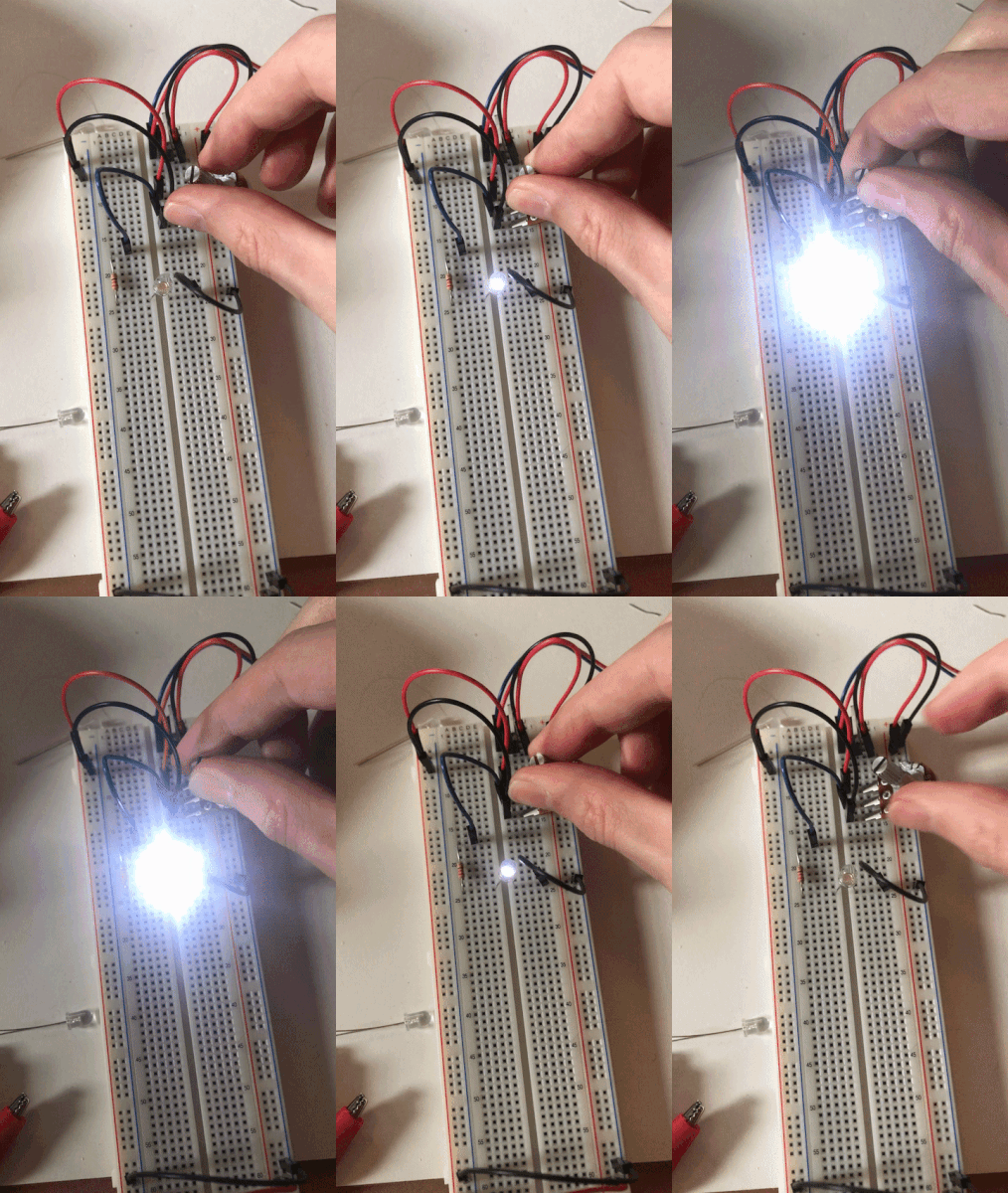
For the final step I built a circuit that uses a potentiometer to control the voltage across the LED. The voltage drop goes from 0 to 5 as the potentiometer is rotated.
