Lab: Digital Input and Output with an Arduino
September 17, 2020
Physical ComputingIn this lab I familiarized myself with the Arduino Nano 33 IoT by wiring a basic circuit and uploading code that would allow me to toggle two LEDs by pressing a button. I began by attaching the Arduino to the breadboard and connecting its +3.3V and ground pins.
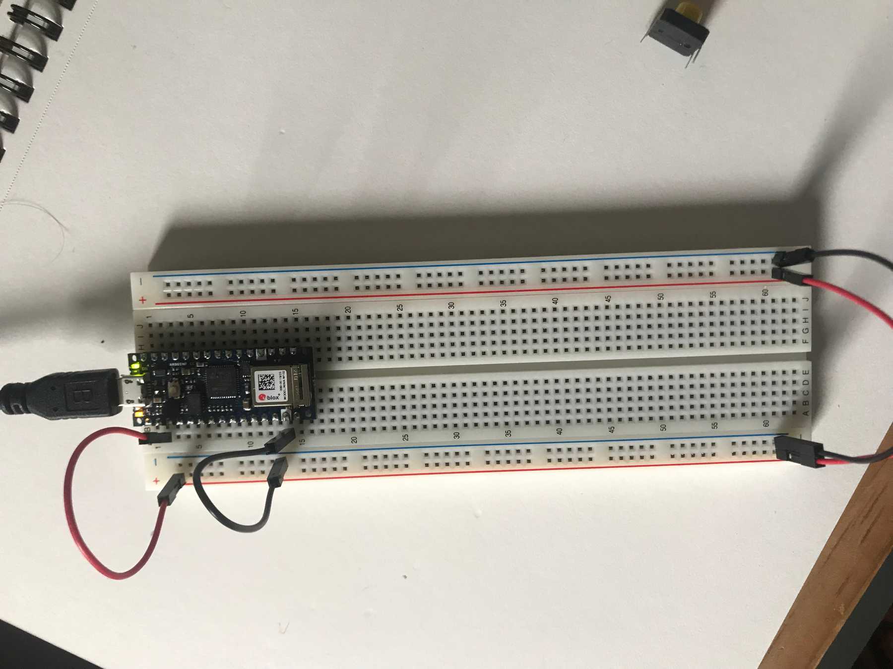 Attaching the Arduino to the breadboard
I started my circuity with a pushbutton connected to the D2 pin and a 10KΩ “pulldown” resistor connected to ground, which prevents the input from behaving unreliably.
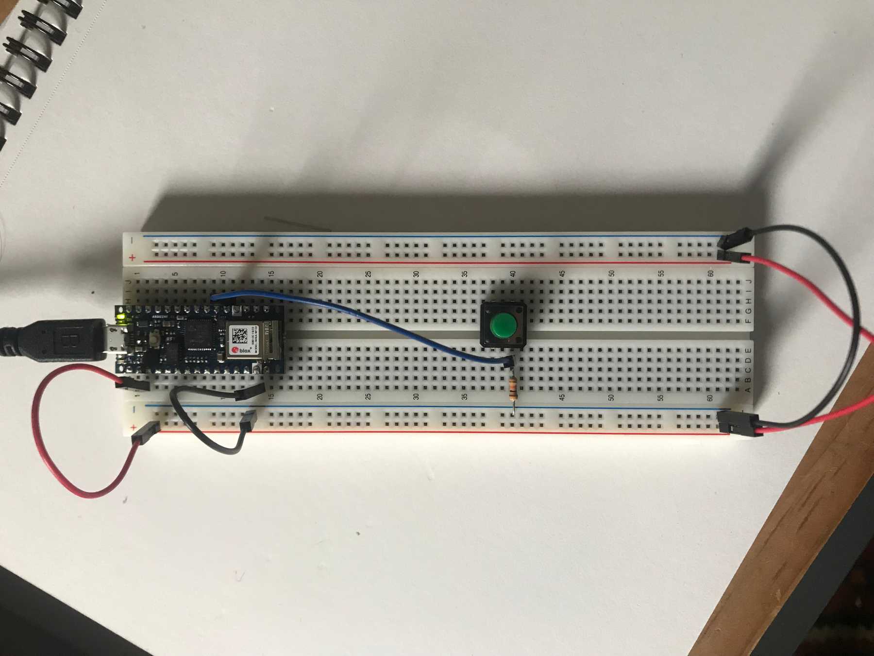 Connecting a pushbutton to pin 2 with a 10KΩ pulldown resistor
Next I connected two LEDs to pins D3 and D4, each wired in series with a 220Ω resistor. These would serve as my digital outputs.
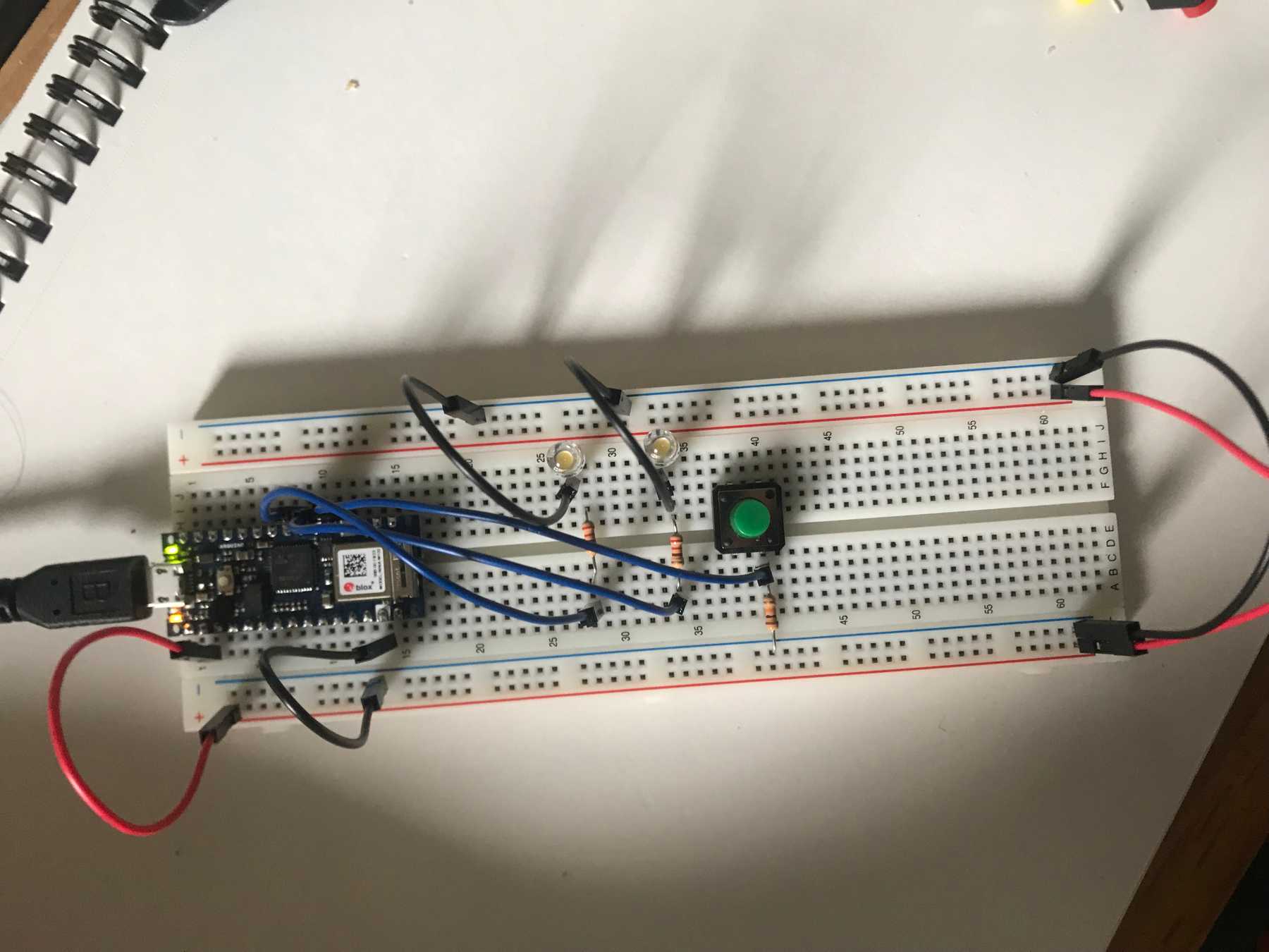 Wiring two LEDs to pins 3 and 4
I was then ready to upload code to the device. Using the Arduino IDE I uploaded this code, which toggles the two LEDs based on whether the pushbutton is pressed:
void setup() {
  pinMode(2, INPUT);    // set the pushbutton pin to be an input
  pinMode(3, OUTPUT);   // set the left LED pin to be an output
  pinMode(4, OUTPUT);   // set the right LED pin to be an output
}

void loop() {
   // read the pushbutton input:
   if (digitalRead(2) == HIGH) {
     // if the pushbutton is closed:
     digitalWrite(3, HIGH);    // turn on the top LED
     digitalWrite(4, LOW);     // turn off the bottom LED
   }
   else {
     // if the switch is open:
     digitalWrite(3, LOW);     // turn off the top LED
     digitalWrite(4, HIGH);    // turn on the red bottom
   }
 }
When the code was finished uploading, the first LED turned on.
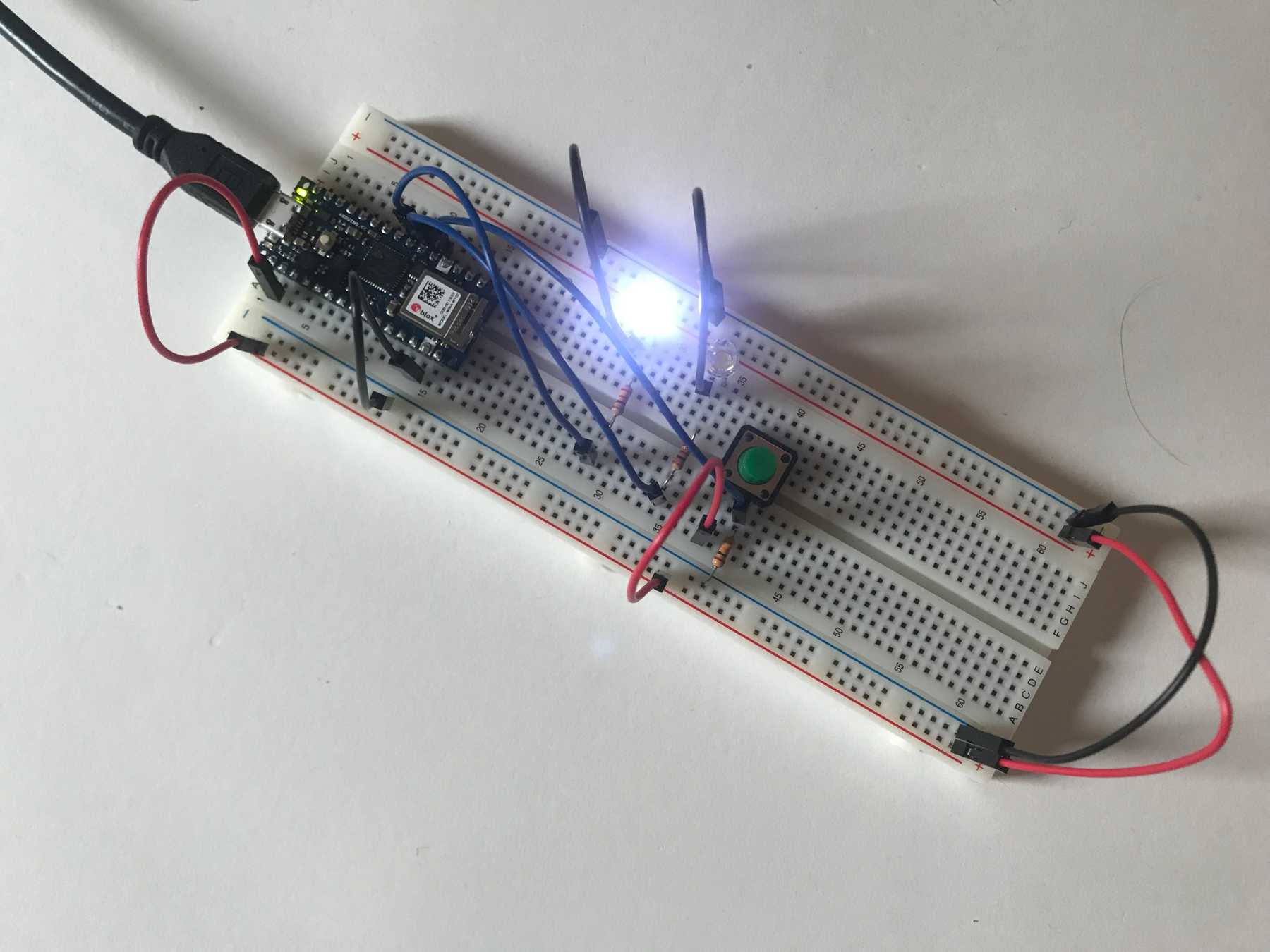 The first LED lights up after uploading the code
The LEDs toggled when I pressed the button.
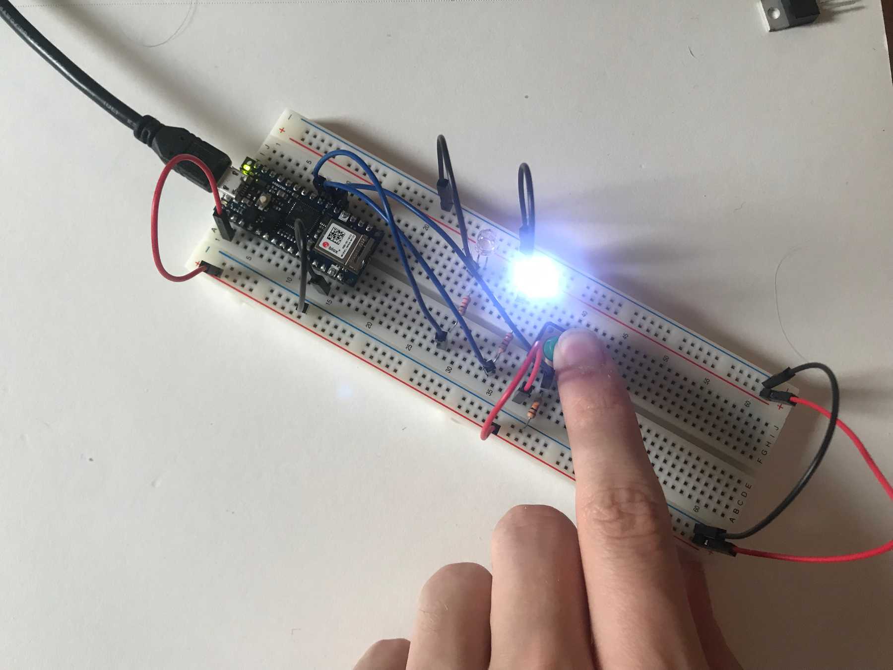 The second LED lights up when pressing the button
Pressing the button causes the LEDs to toggle