Abacusynth: PCB Development
April 11, 2022
Homemade HardwareThesis
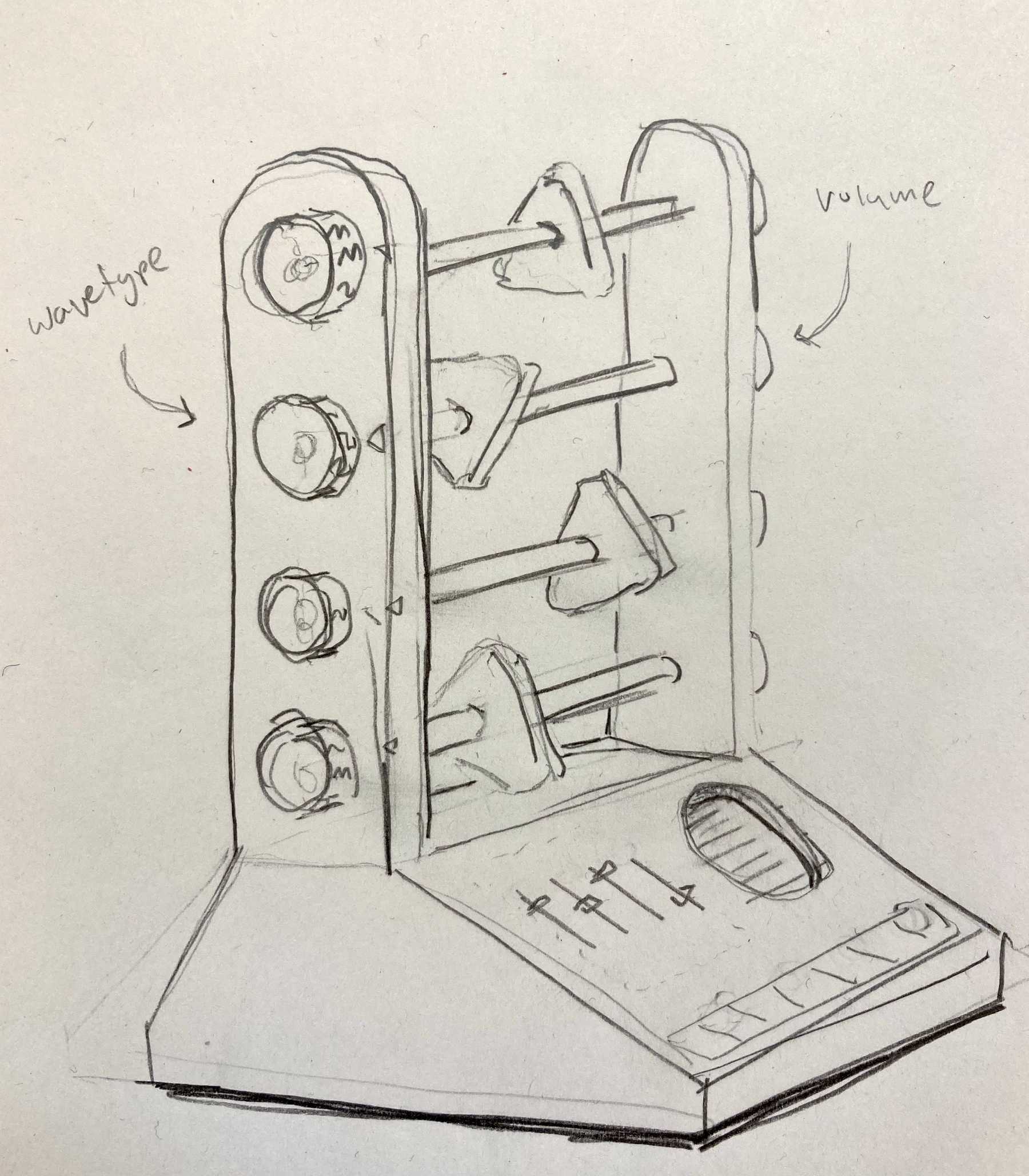 Sketch of my thesis project: Abacusynth
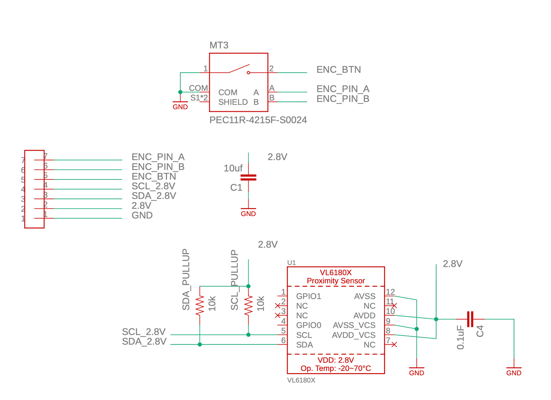
For my thesis project I am creating a synthesizer inspired by an abacus. Its interface consists of four rods, each holding a spinning object. These four objects represent oscillators in the synth. A user can spin them and move them left and right along the rod. Each rod needs a distance sensor facing inwards to measure the object’s position and an encoder facing outwards which is used to adjust the harmonic of the oscillator and change the waveform. A breakbeam sensor is used to detect rotation, but this is separate from the PCB — for that I am using these sensors.
Board Design
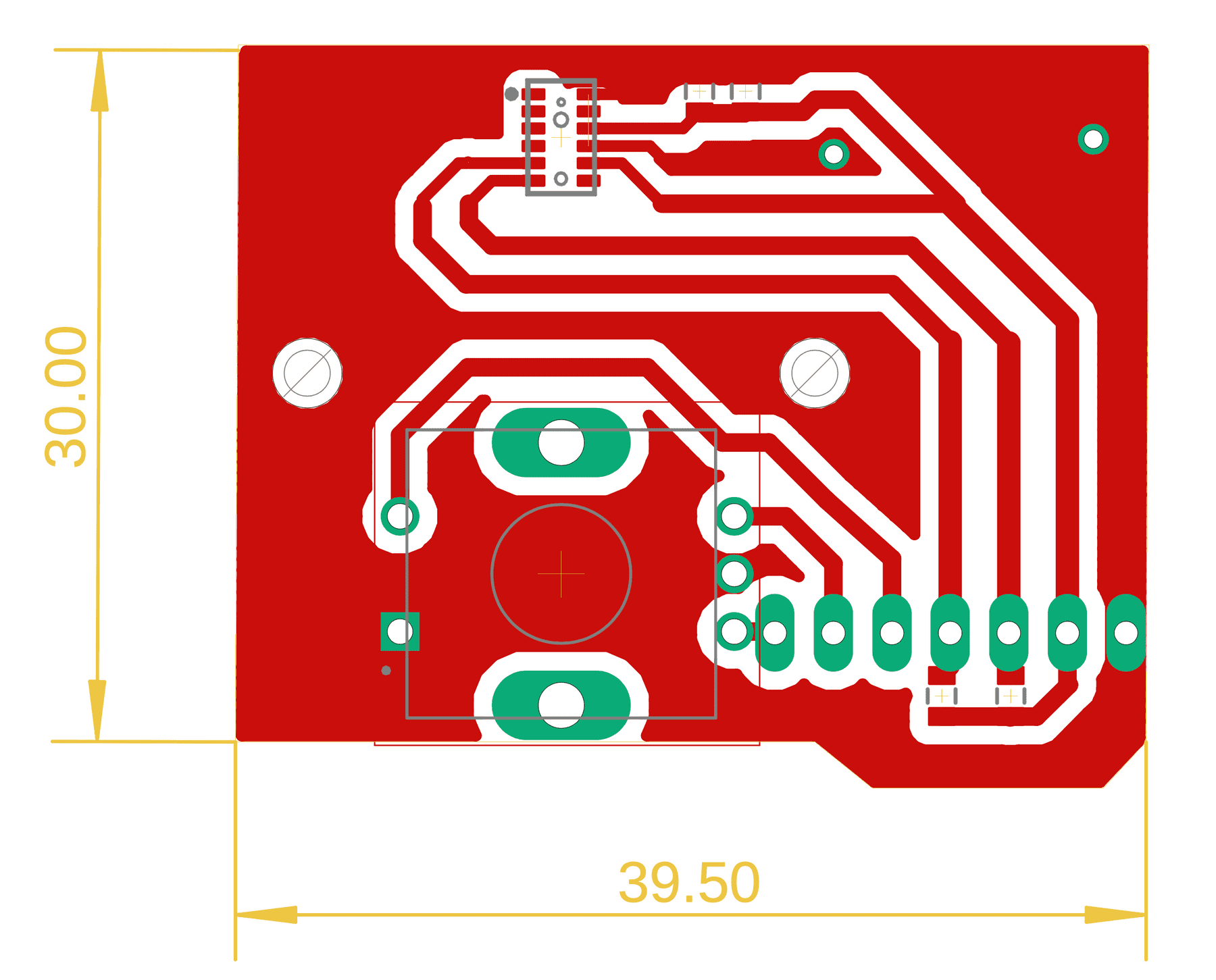
The board runs on 2.8V — a requirement of the VL6180X distance sensor. It is single sided, since the sensor faces forward and the encoder sits on the back, meaning all connections are on the front. The schematic is pretty simple, including pulll-up resistors for the SDA and SCL connections and capacitors to help smooth the signal.
Bill of Materials
| Part | Value | Device | Package | Description |
| C1 | 10uf | COMPONENT_CAP-0805 | 0805 | Capacitor |
| C4 | 0.1uF | COMPONENT_CAP-0805 | 0805 | Capacitor |
| MT3 | PEC11R-4215F-S0024 | PEC11R-4215F-S0024 | XDCR_PEC11R-4215F-S0024 | Incremental Encoder, 12 Mm, Contact Rating 10 Ma - 5 Vdc Check availability |
| SCL_PULLUP | 10k | COMPONENT_RESISTOR-0805 | 0805 | |
| SDA_PULLUP | 10k | COMPONENT_RESISTOR-0805 | 0805 | |
| U$1 | HEADER-7-DIP | HEADER-7-DIP | HEADER-7-DIP | NPTC081KFXC-RC: Vertical Female SMD Headers |
| U1 | VL6180X | VL6180X | VL6180 | VL6180x Proximity and Light Sensor with Gesture Recognition |
Milling V1
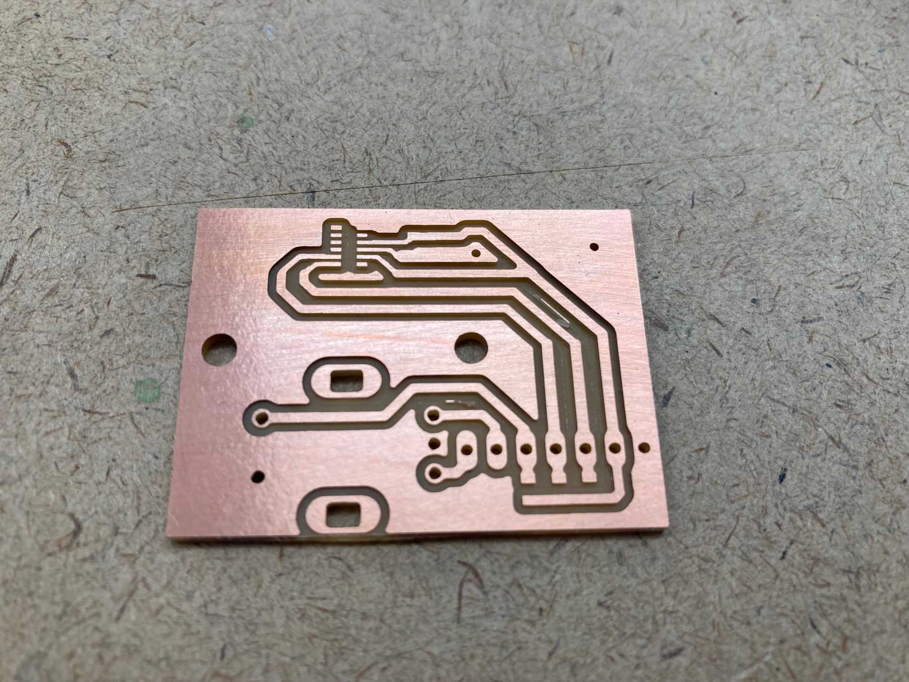
To start I milled one board to make sure everything worked.
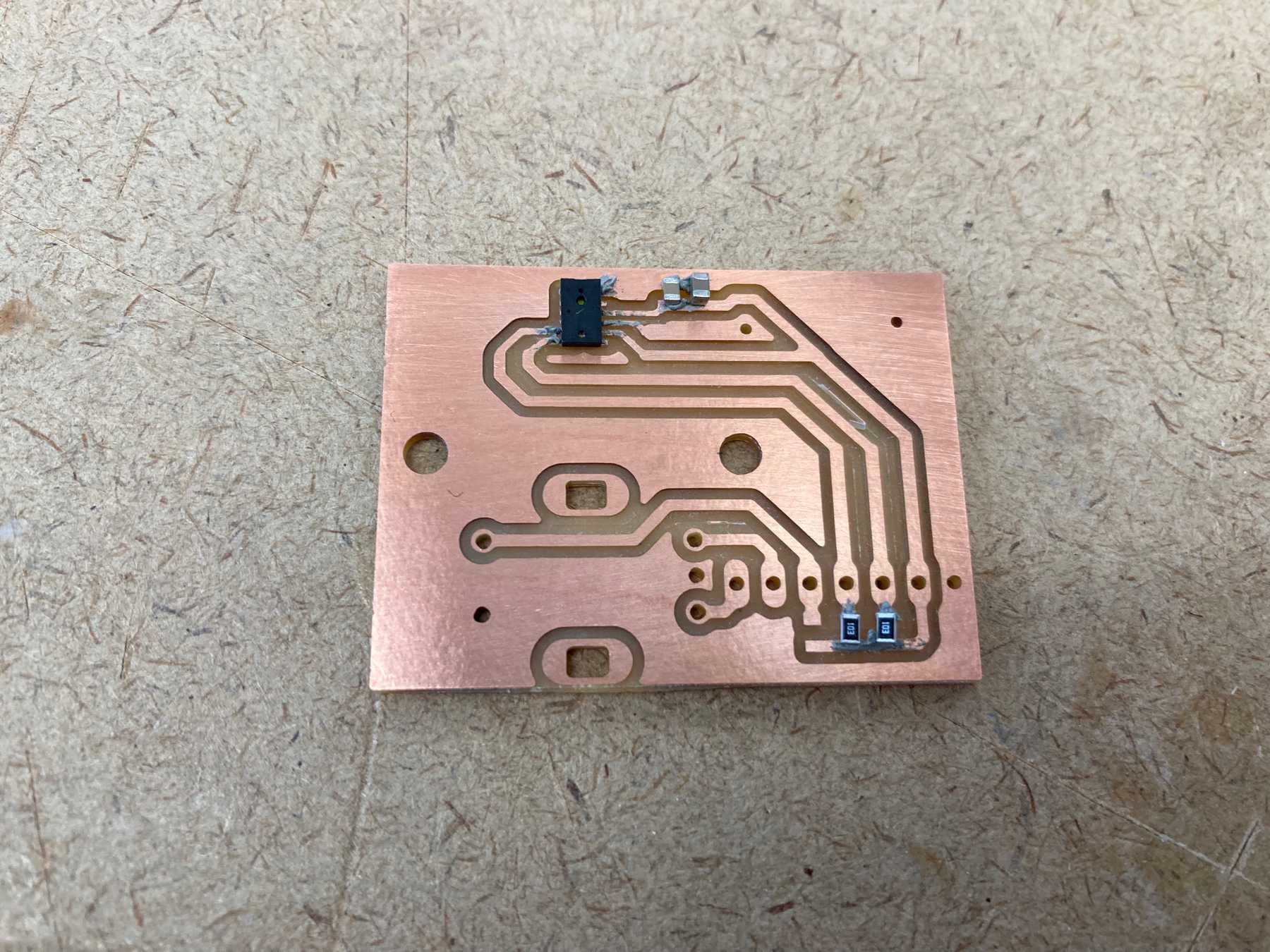 Adding the components with solder paste
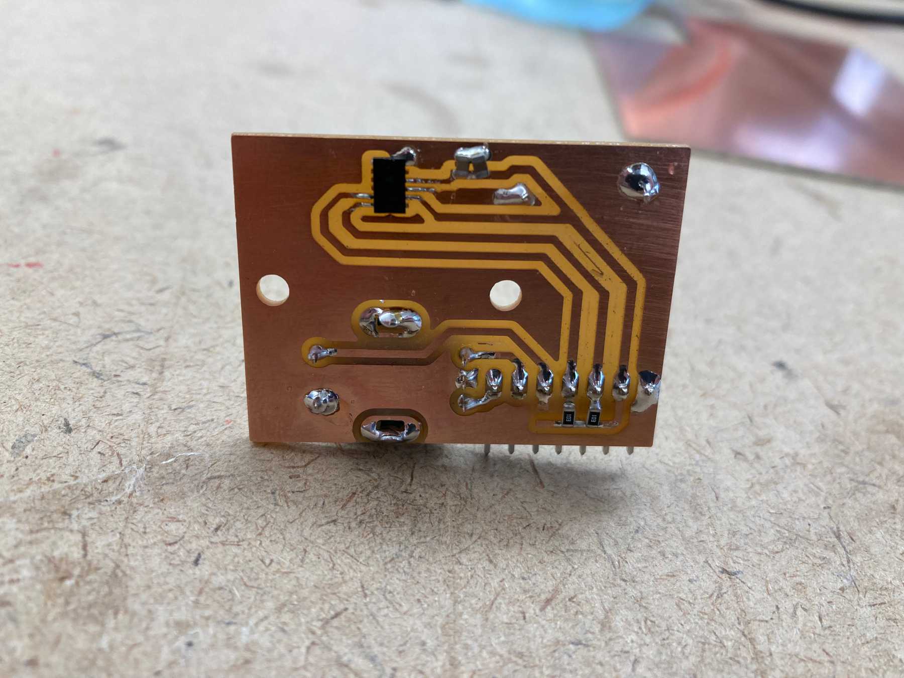
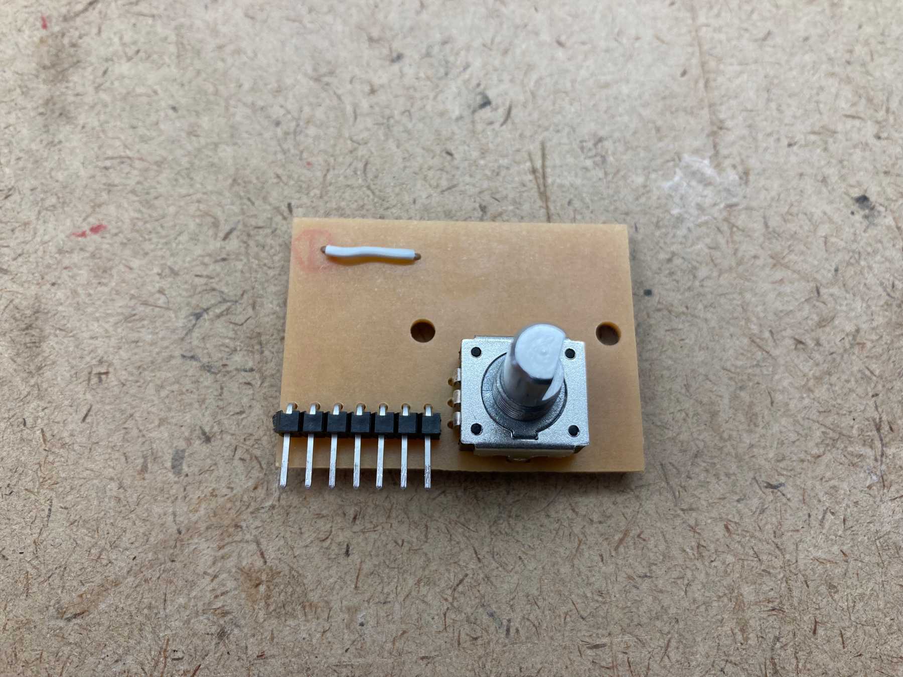
I added the components by hand with solder paste and soldered them with the heat gun. I then soldered the larger components with the iron.
Once everything was connected I tested the board by connecting 2.8V power and the sensors to my main board. It worked!
Testing the distance sensor
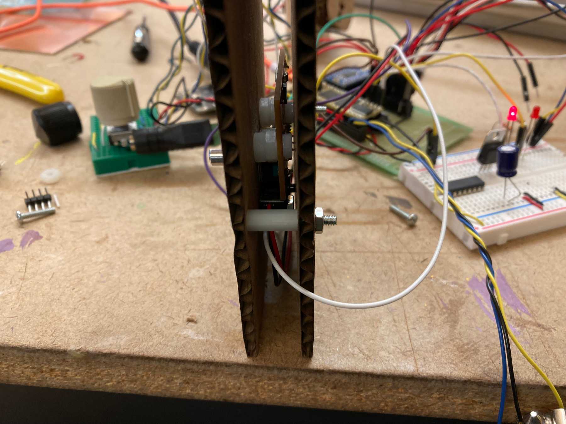
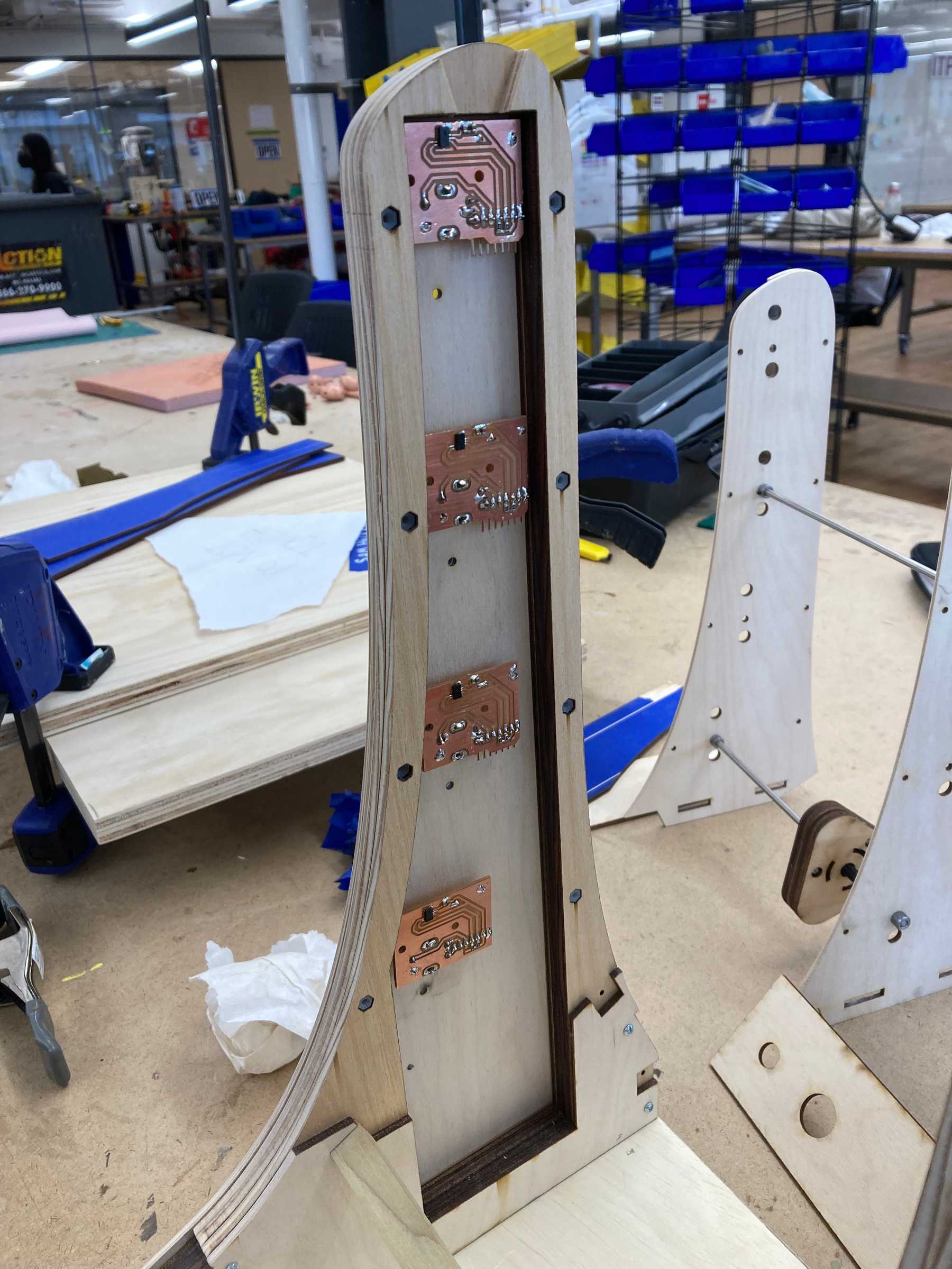
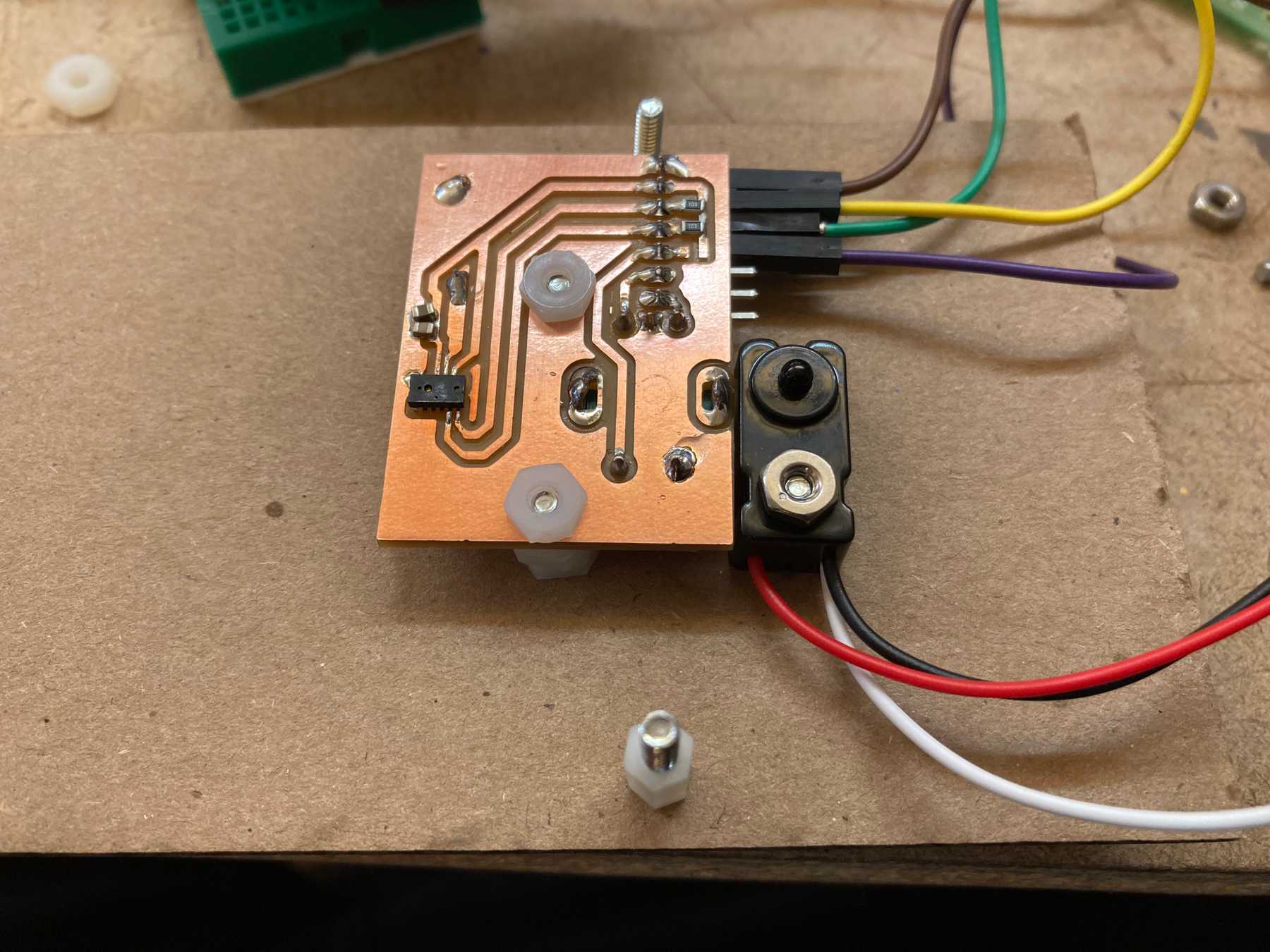 The board mounted on the inner wall
The mounting configuration with the breakbeam sensor attached.
One limitation I noticed was that the distance sensor picked up on the inside of the wall if it was any thicker than a half inch thick. I had initially thought that the thickness would be a bit wider, giving me more room for the wiring.
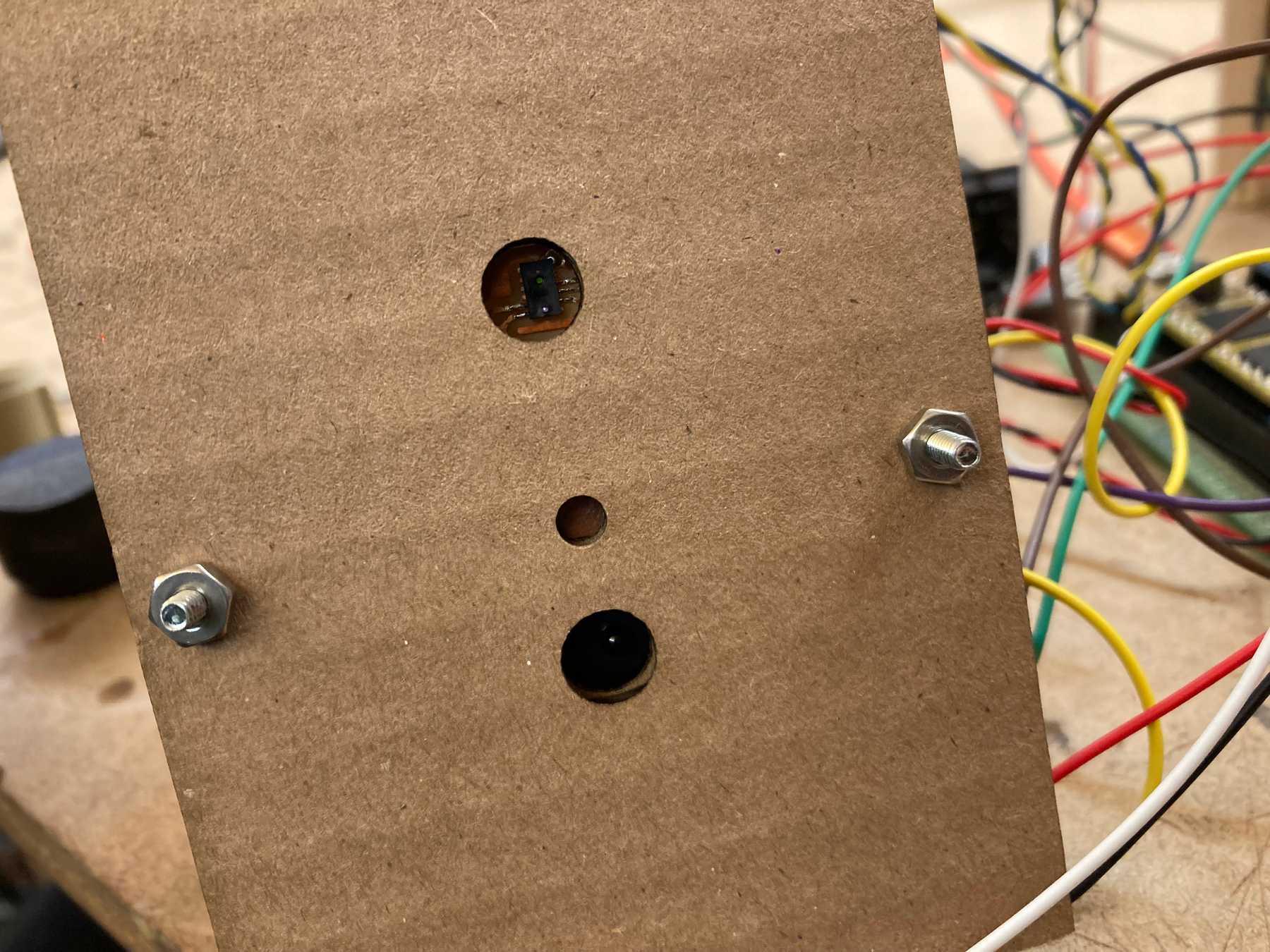 The distance sensor aligns with the hole
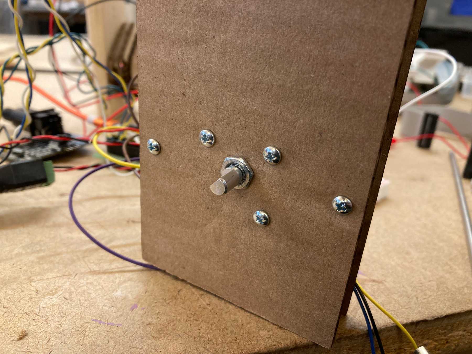 The other side screws into the board and encoder
Multiples
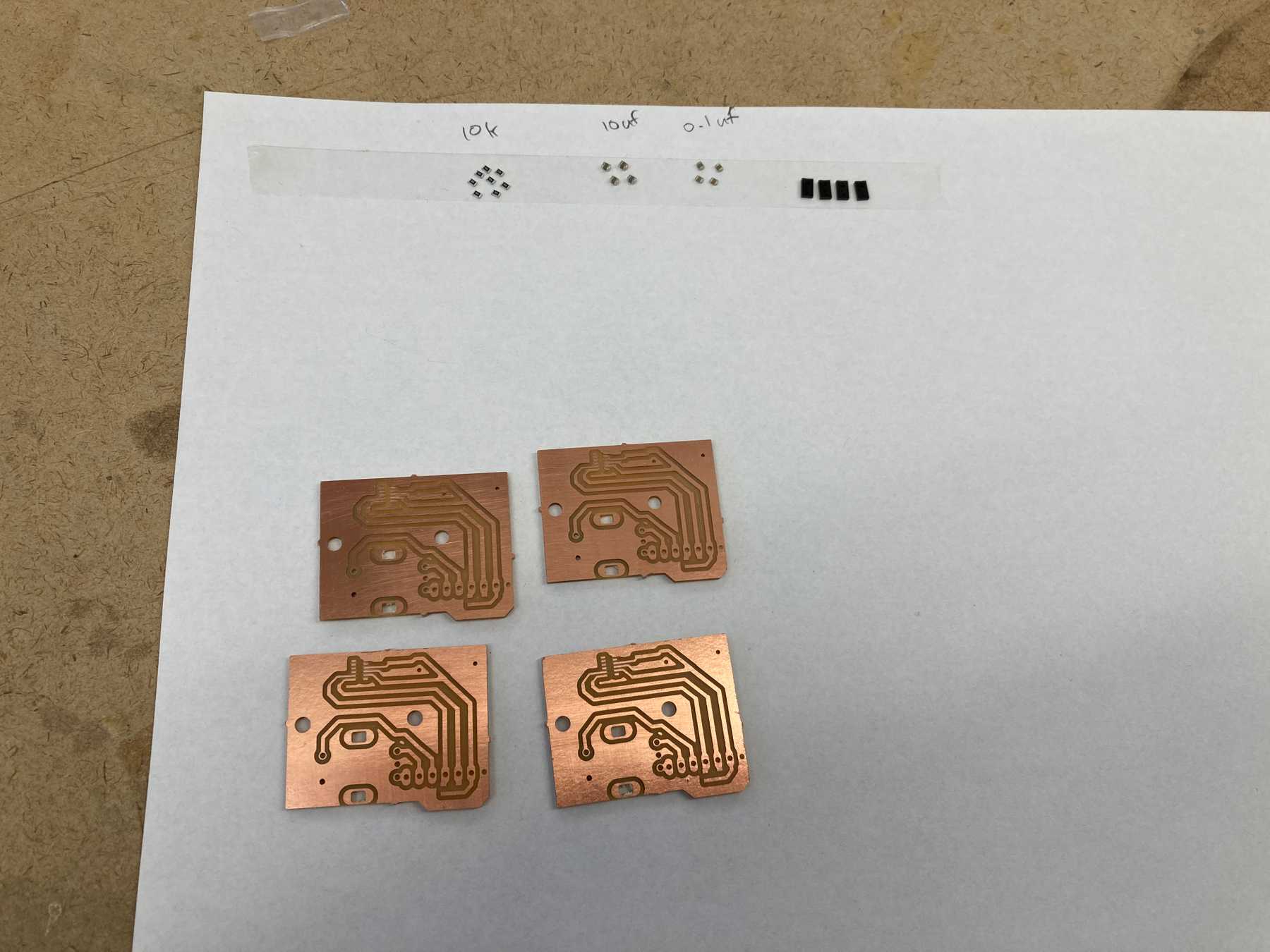
Now that I was sure the design worked, I needed to multiply it x4.
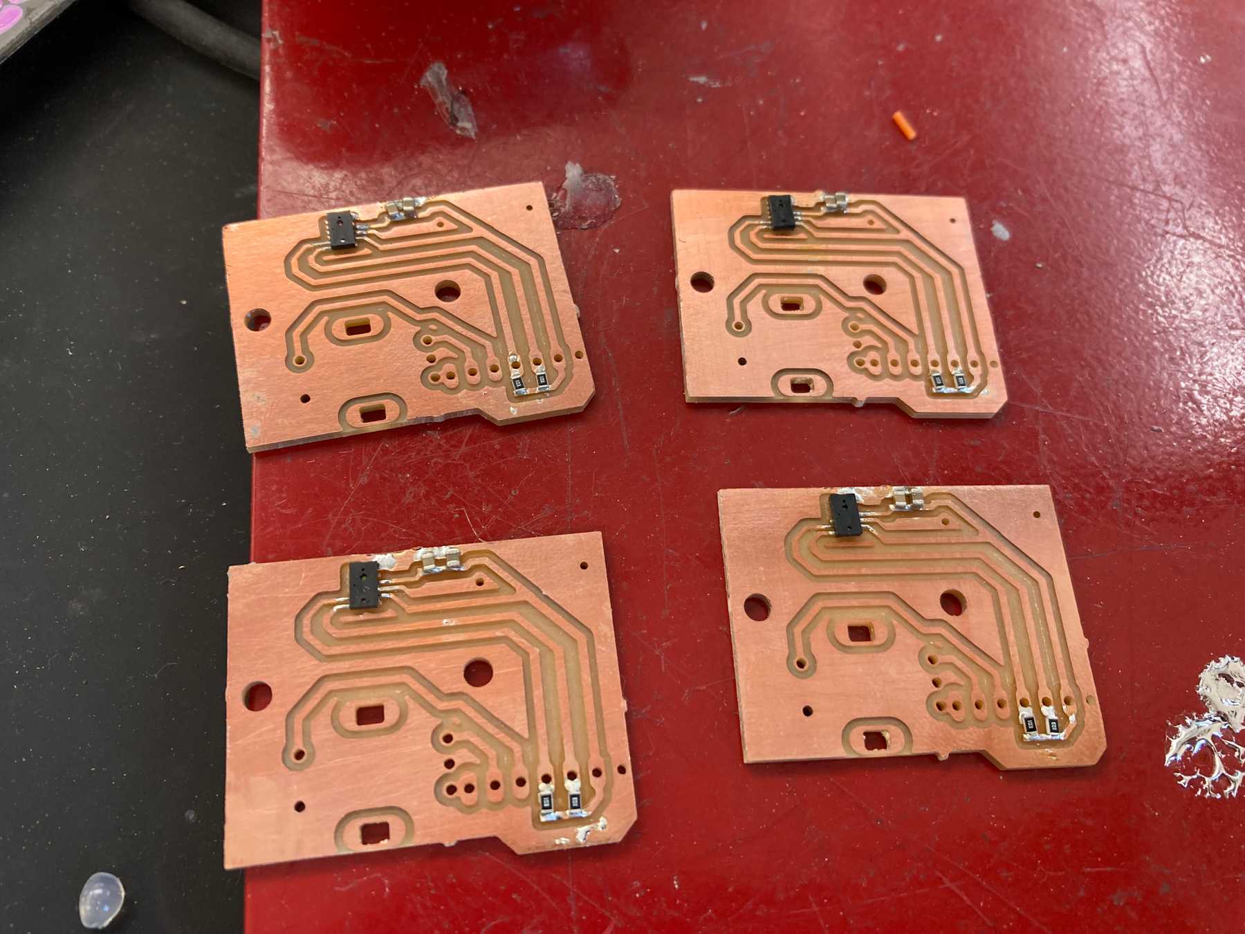
The milling went pretty smoothly. Since there aren’t too many parts, I added them by hand.
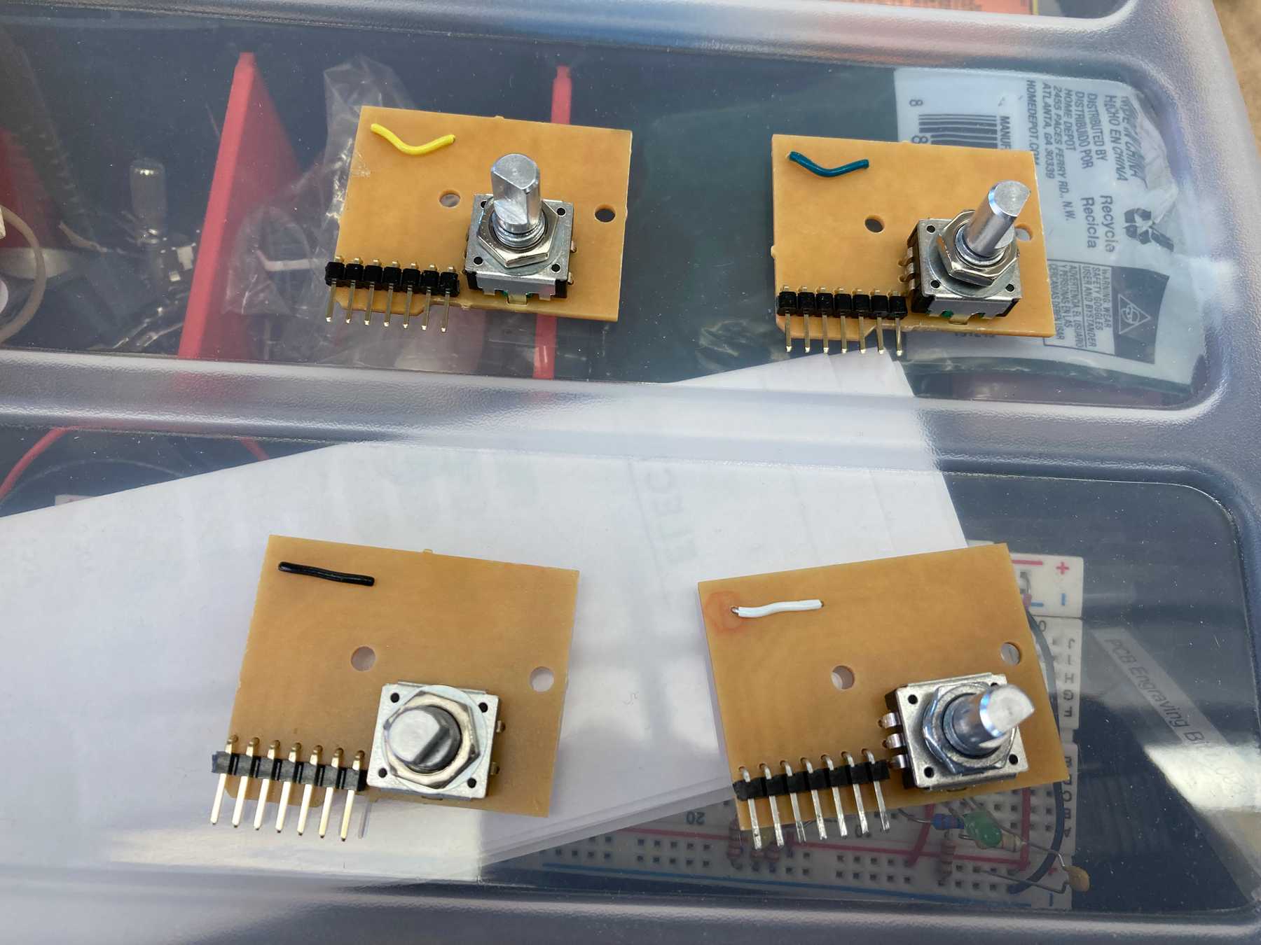
I then tested each one by connecting it to my circuit. Out of the four new boards, all but one worked. So I kept my first prototype and soldered the encoders to the 3 new working ones.
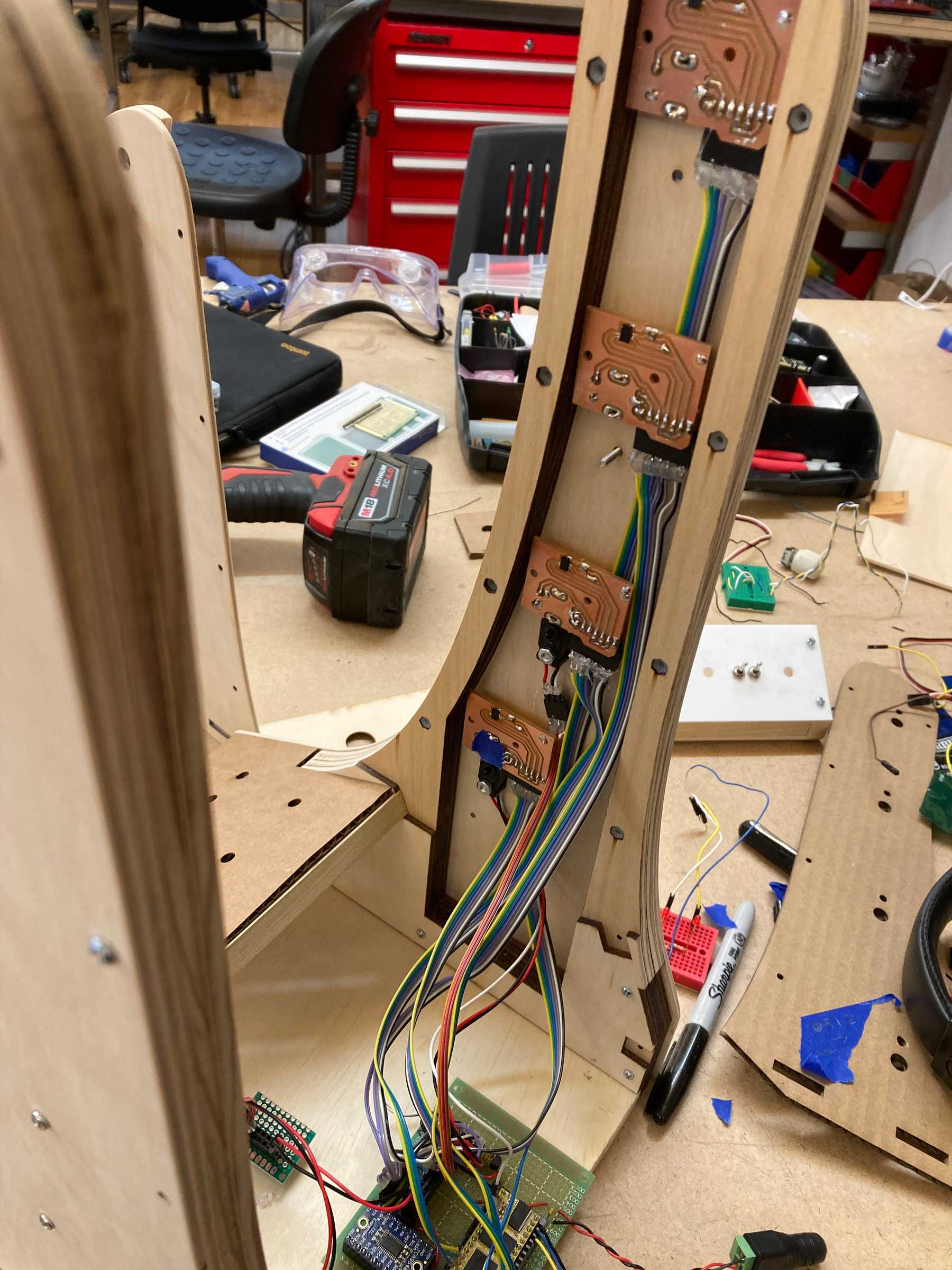
I mounted the components fit in the new wooden housing and wired everything up. It was a little tight but everything fit.
