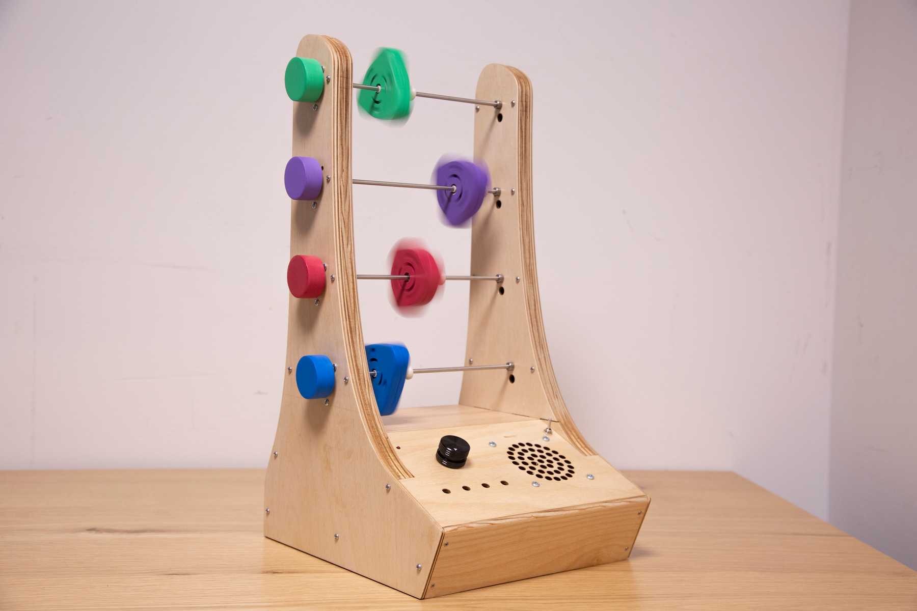
Abacusynth: Housing Fabrication
May 04, 2022
ThesisMy thesis, the Abacusynth, is a synthesizer inspired by an abacus.
First Prototypes
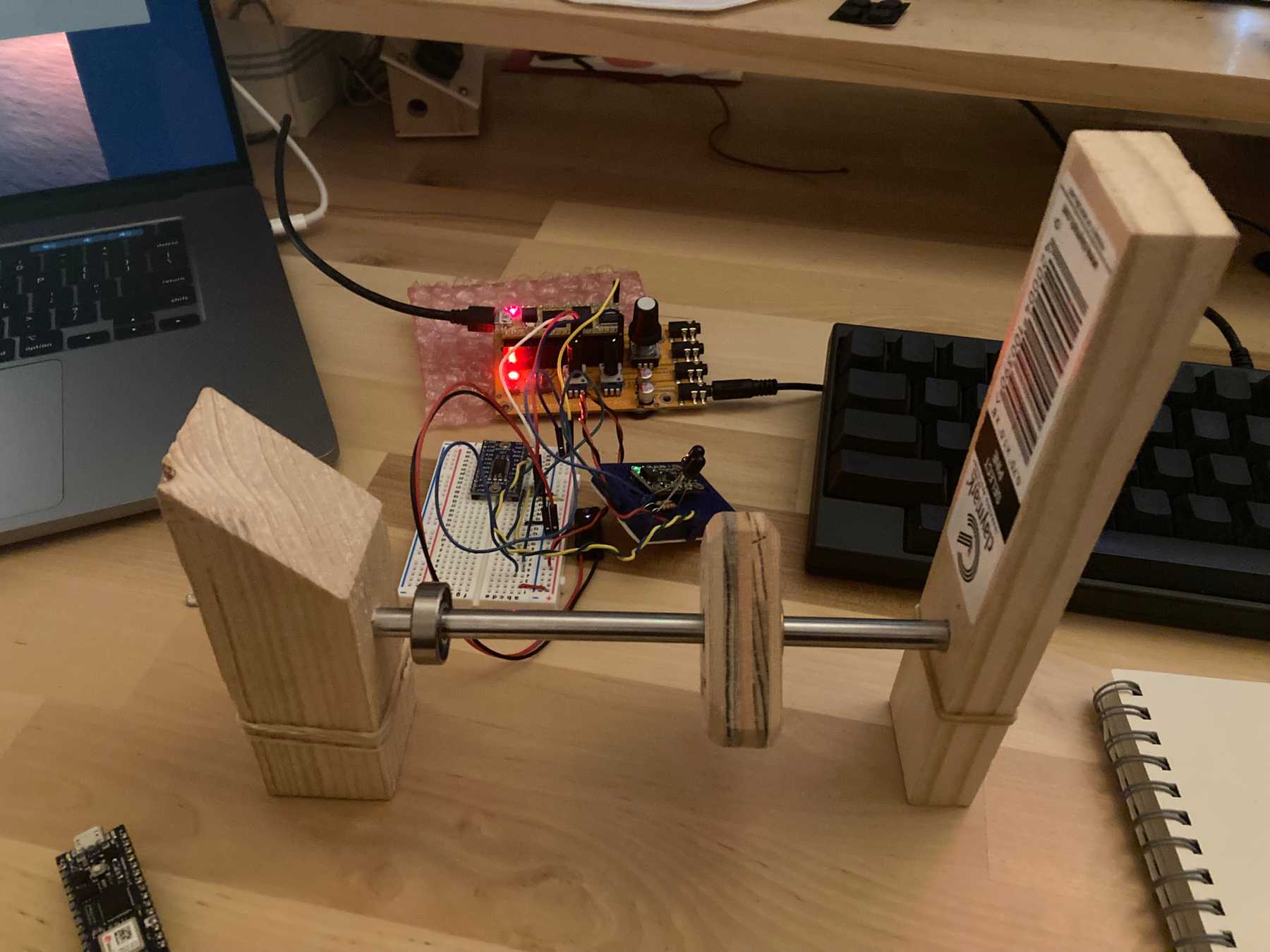
I began with some scrap wood connected by a steel rod, and I used small breadboards mounted with rubber bands to hold the sensors in place. I was using a time-of-flight sensor to measure distance and a breakbeam IR sensor to measure rotation.
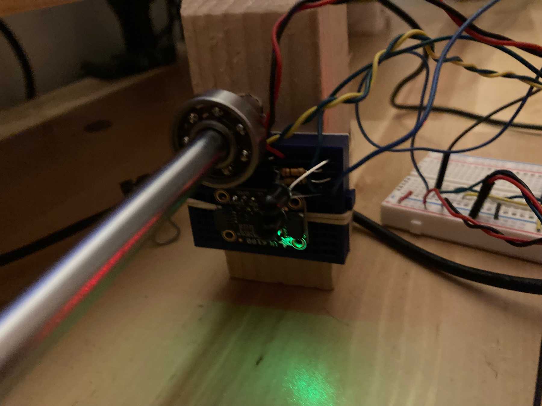 Prototyping the sensor with a rubber band
Designing the Enclosure
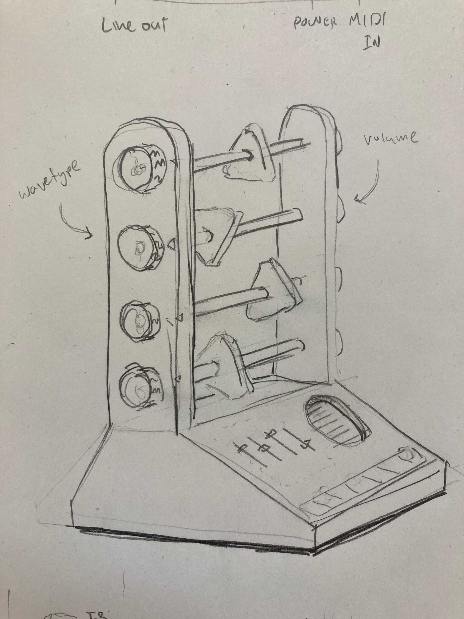
I sketched out what I wanted the final enclosure to look like. Initially I wanted knobs on both sides, one to control the waveform, and one to control the volume. This changed pretty quickly, since that added a lot of complexity. I opted for rotary encoders with push buttons so that I could combine multiple controls in a single knob.
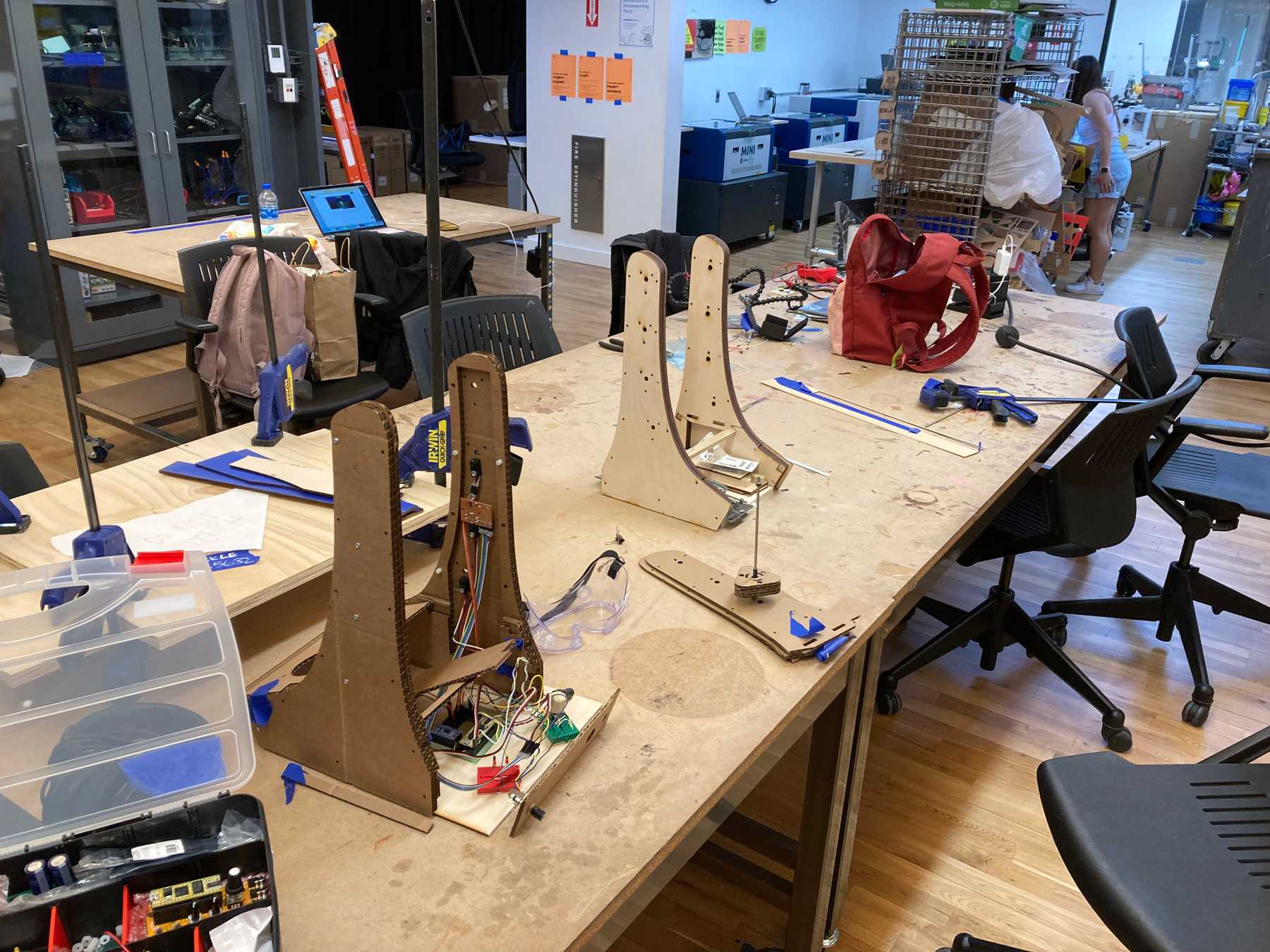
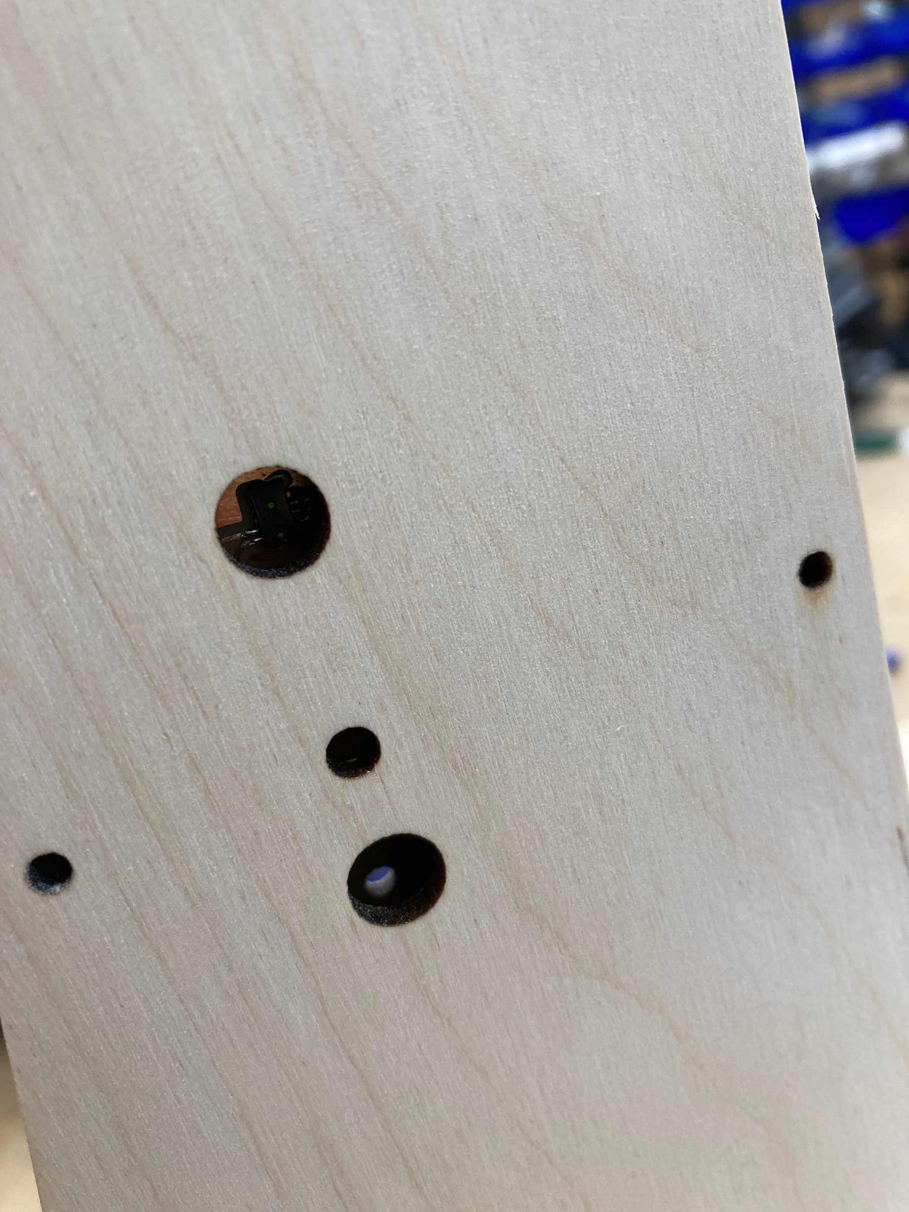
The first thing to do was to design the walls that hold the sensors and rods. I started with a cardboard rectangle with holes for the sensors: the distance sensor on top and the break-beam on the bottom.
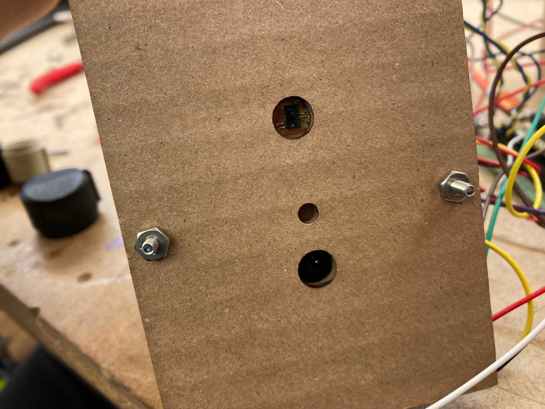 Testing the sensors with laser cut cardboard
Once that was working a moved on to wood. The inner section would be removable, since it would not need any electronics — it would just hold the rods and spinners.
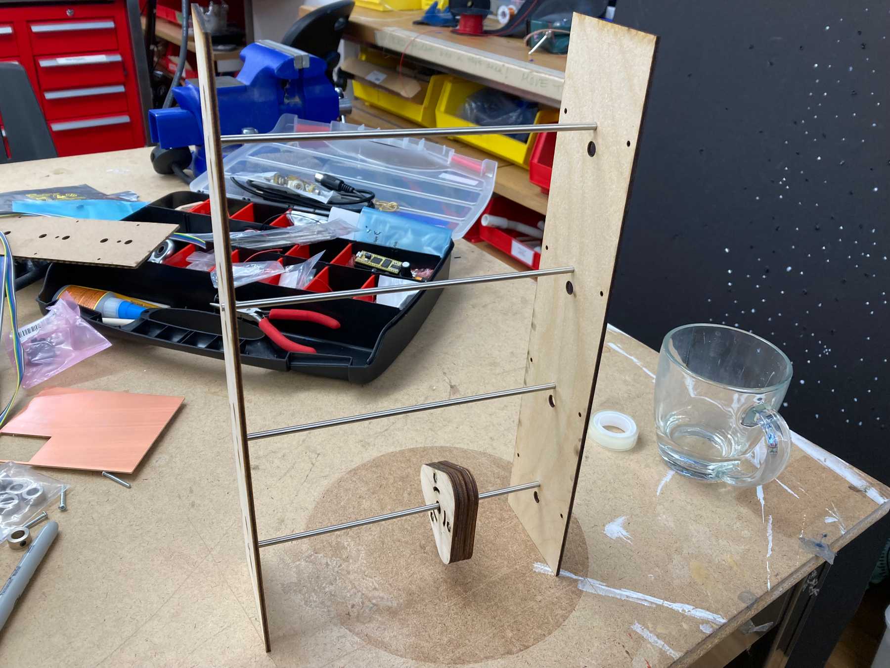 The first wooden inner section
I used 1/2” standoffs to connect the inner and outer sections. The PCB boards fit pretty snugly inside.
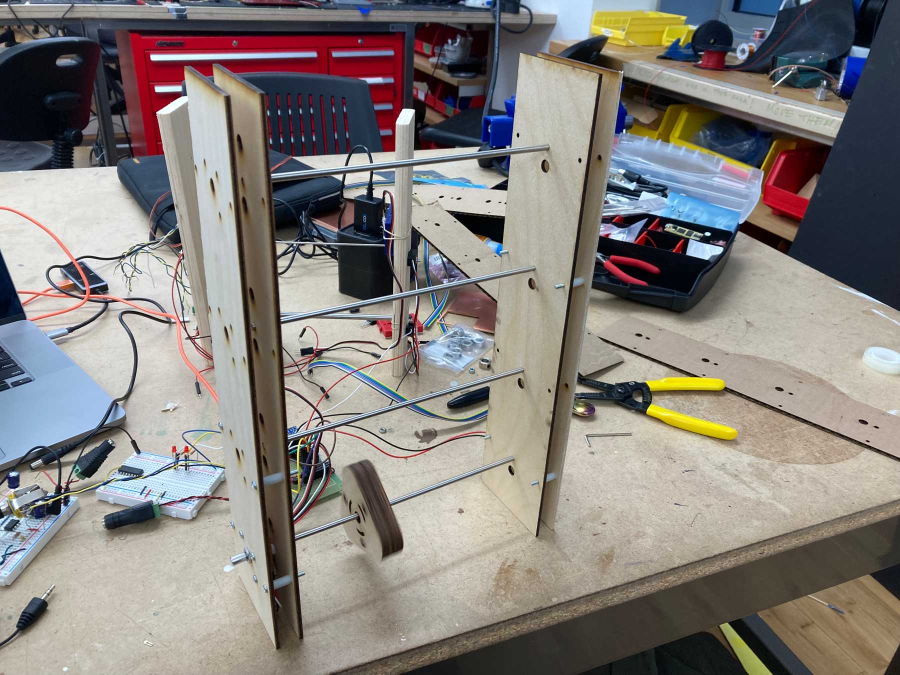 Building the wall structure with sensors in between two layers of wood
New Design
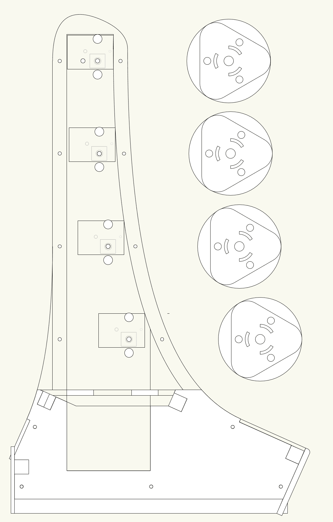
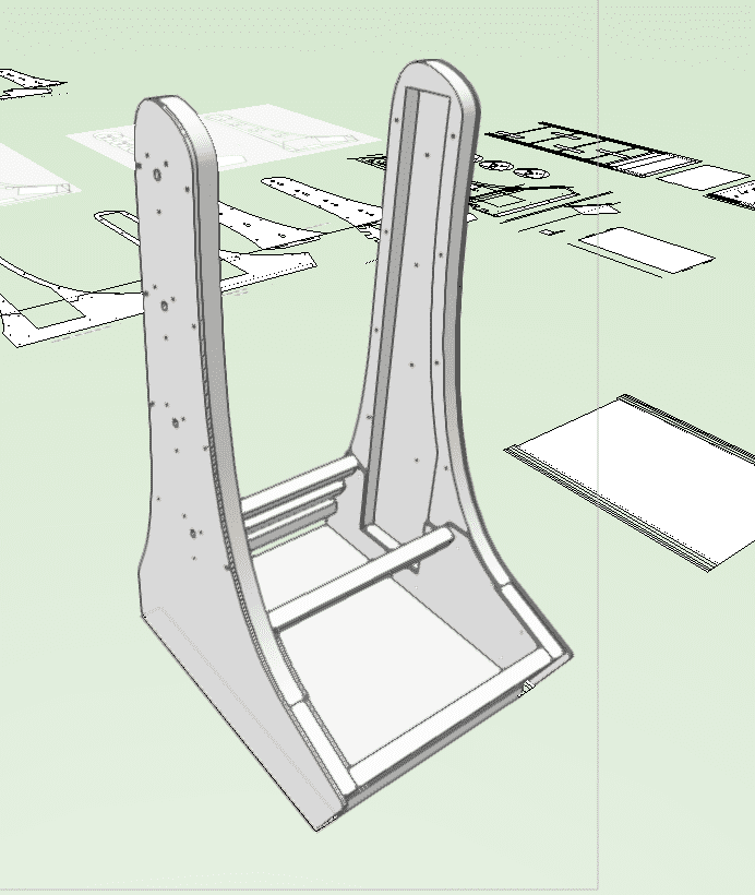
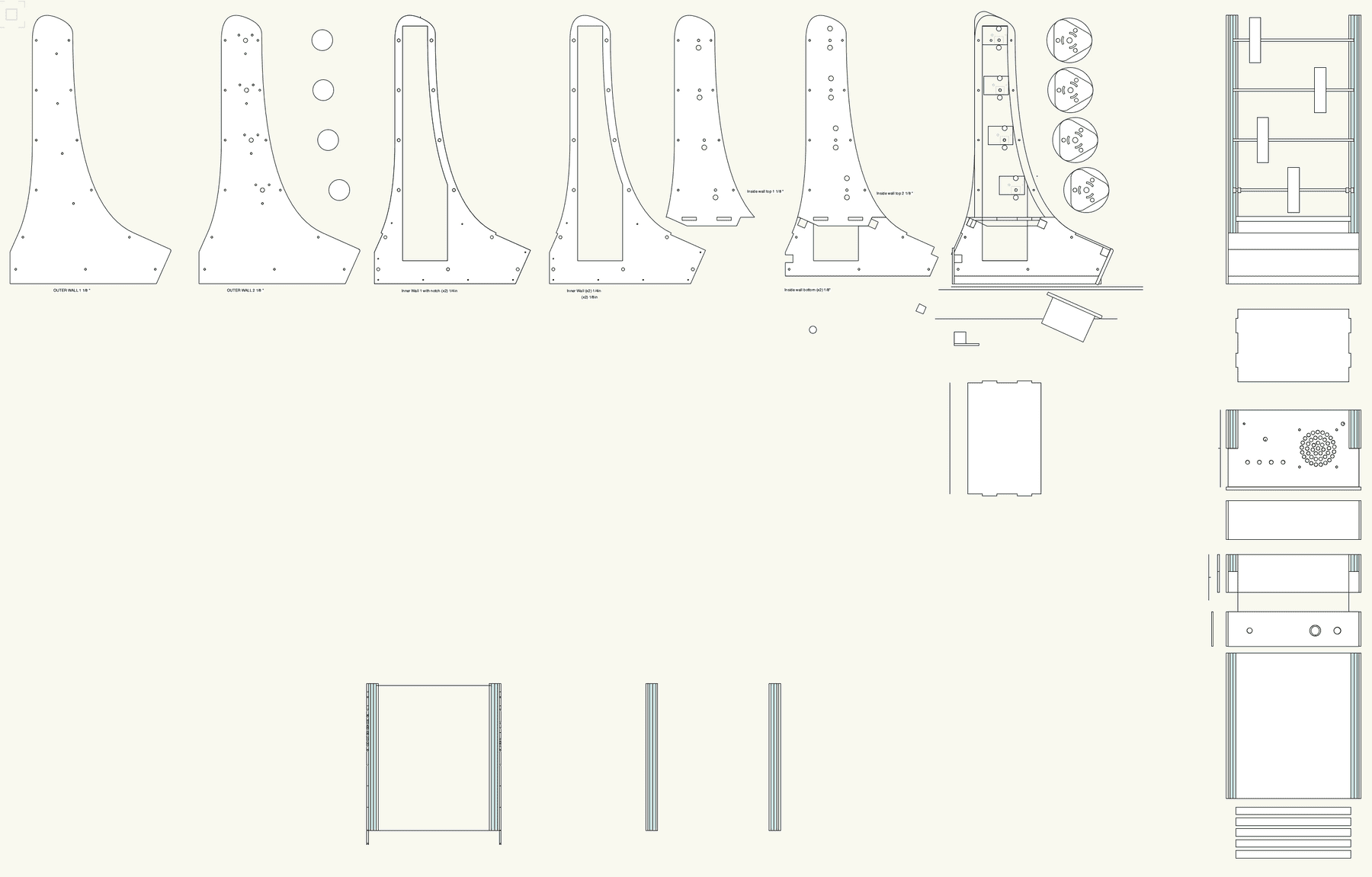 Designing multiple layers in Vectorworks
With the prototype working, I designed the final enclosure in Vectorworks. It consisted of multiple layers of wood that would stack to create the hollow walls.
The walls would be connected by 1/2” square dowels that I would cut by hand. They would fit within the square cutouts on the inner layer. The base would be 1/2” plywood, also cut by hand. I created a 3d render to make sure everything fit together.
I then arranged the panels for laser cutting. The inner wall sections would be made up of two 1/4” (really 0.2”) pieces and one 1/8” (really 0.12”) to add up to just over 1/2”, and the outer panels are all on on 1/8” wood.
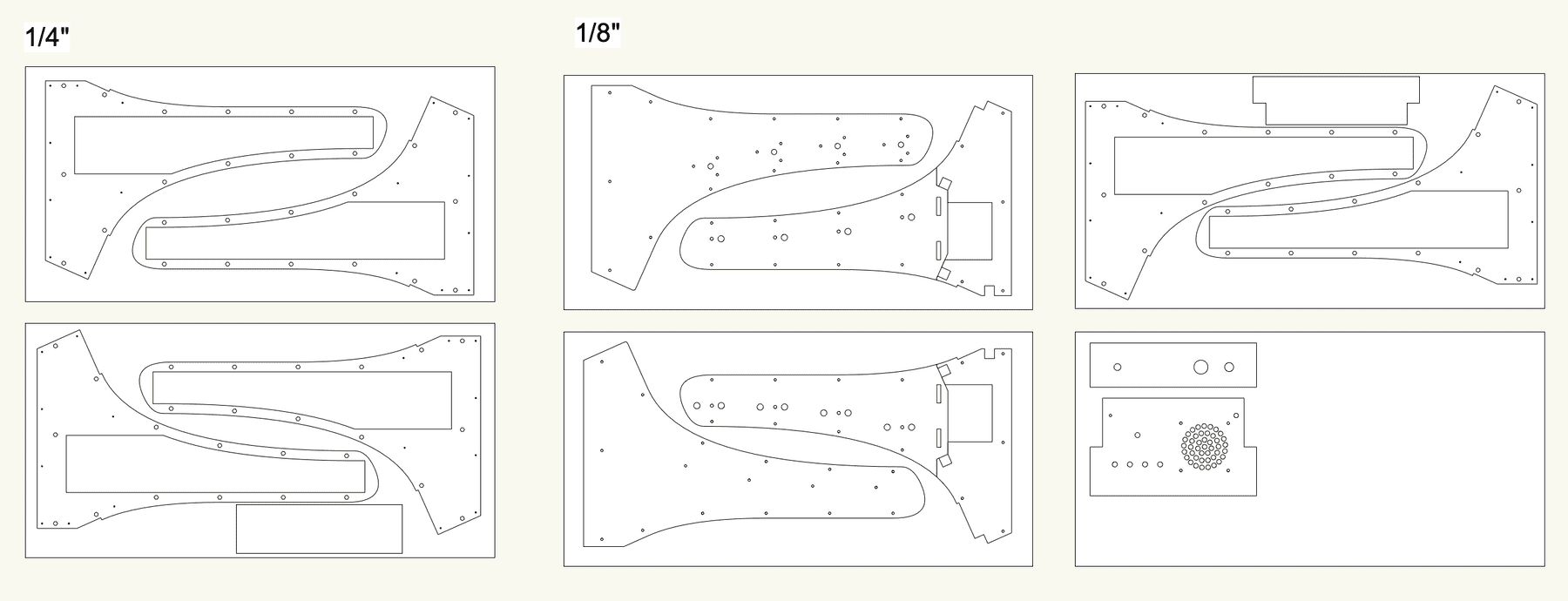 Arranging the design for laser cutting
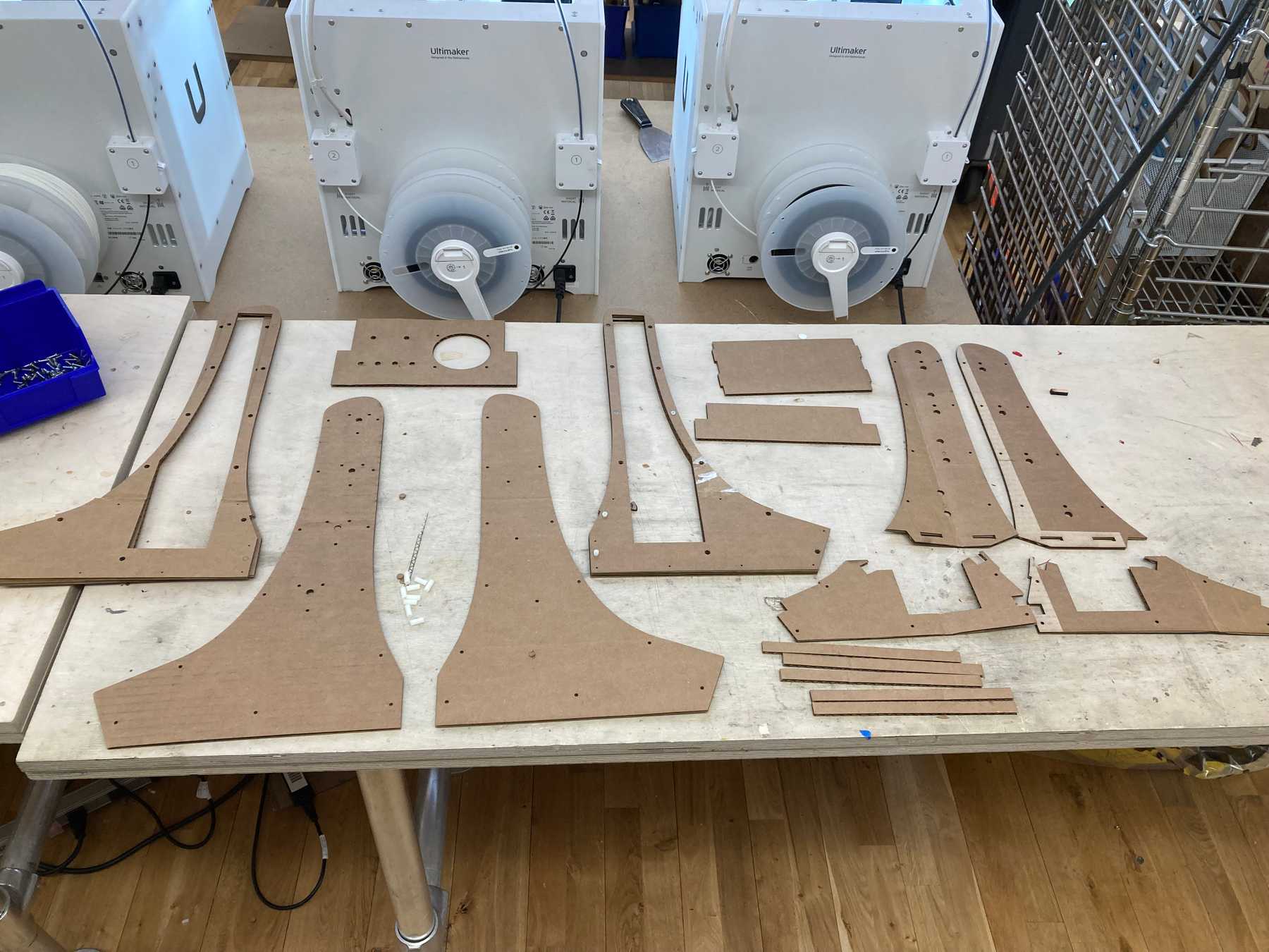
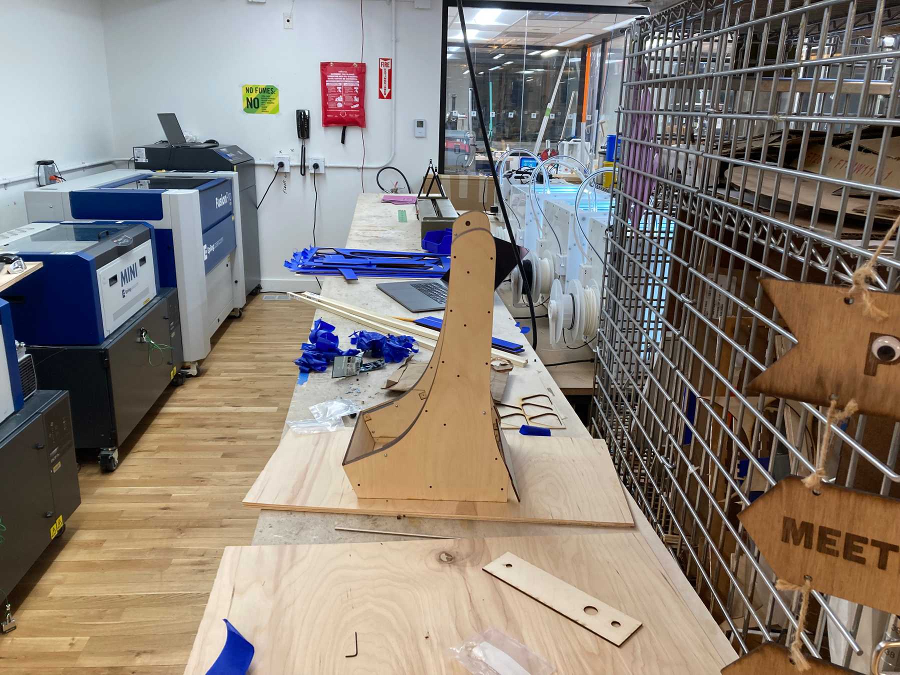
Time to cut! I started with cardboard to make sure the design worked.
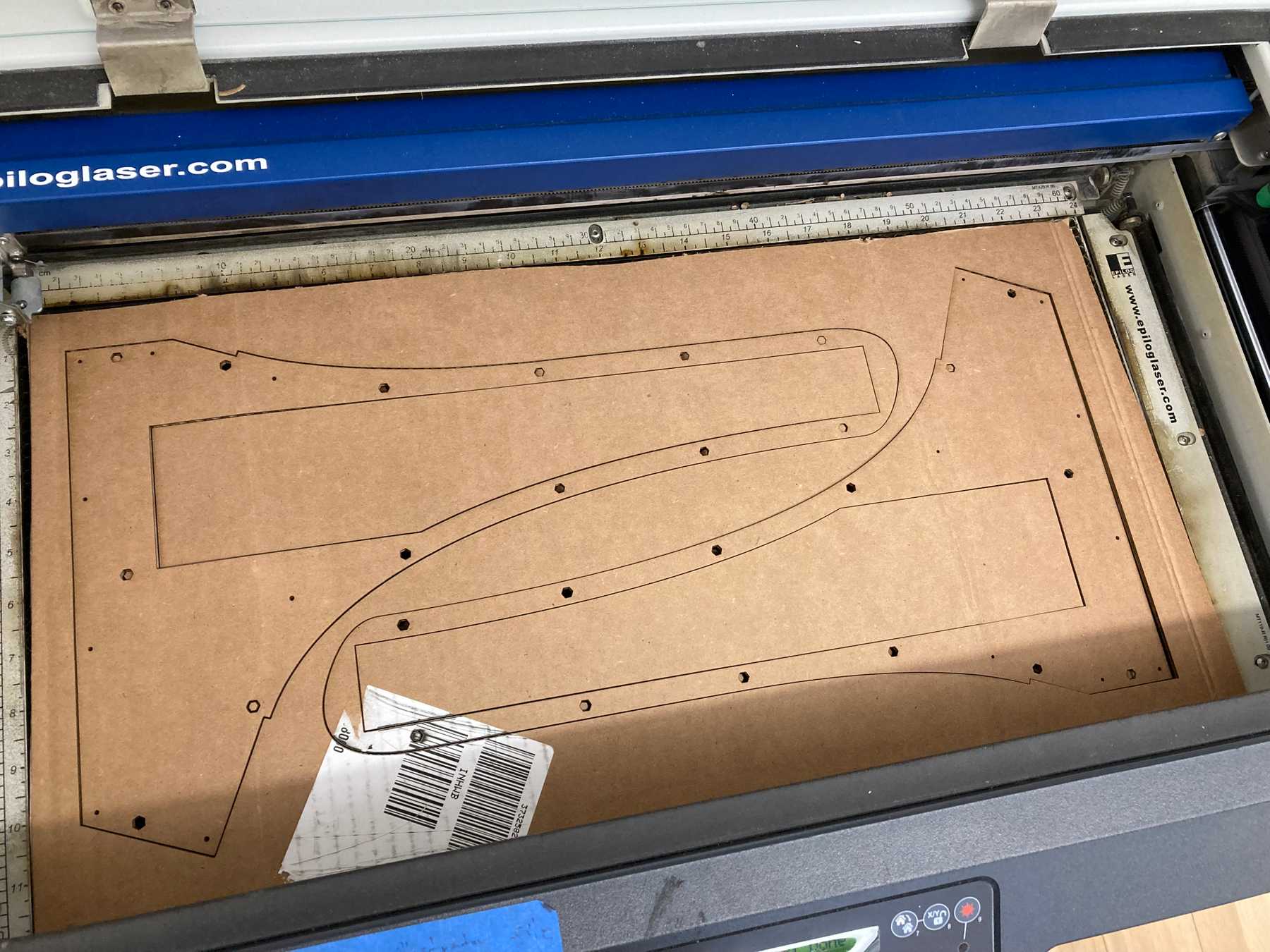 Laser-cutting the new design in cardboard
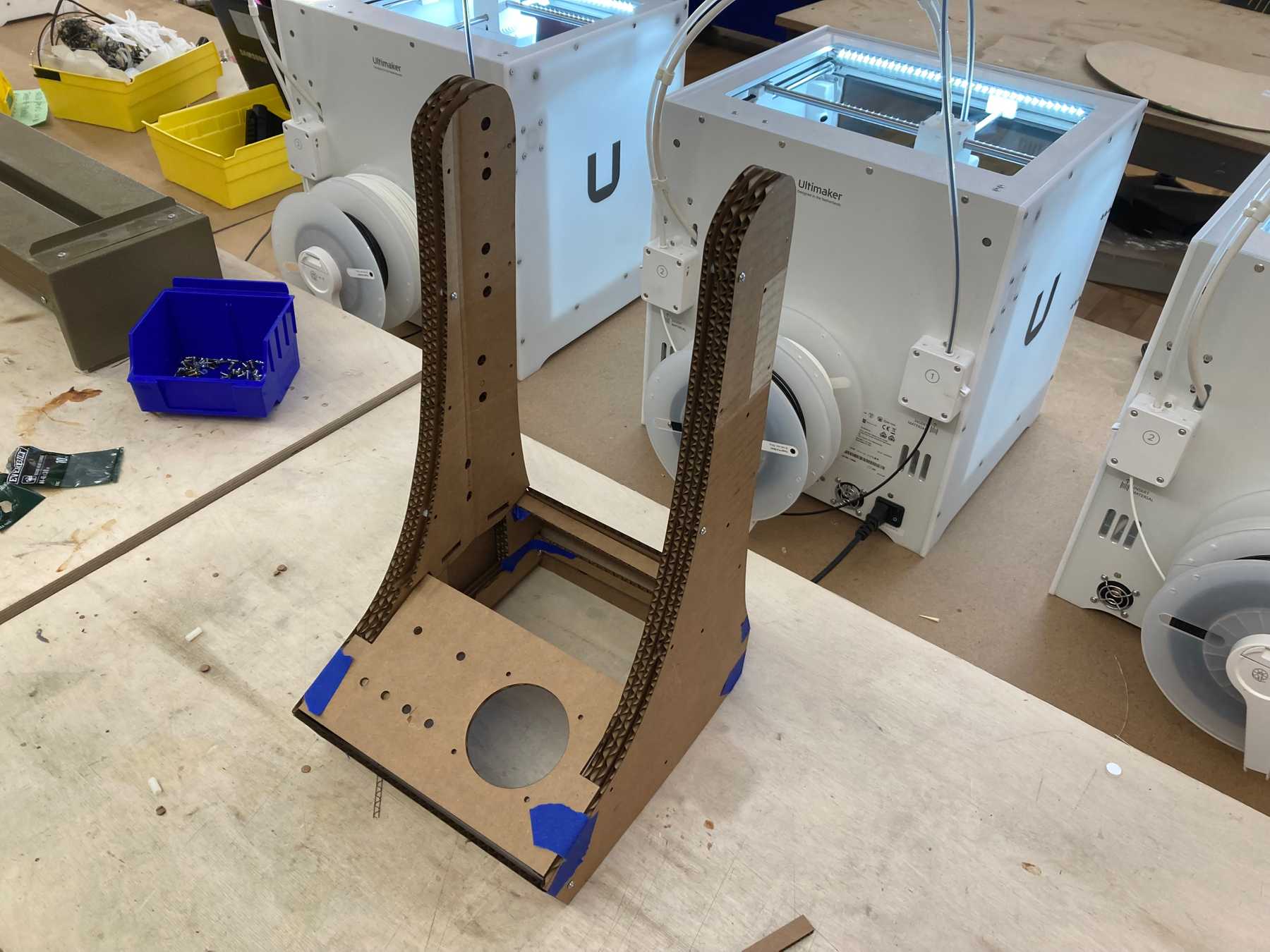
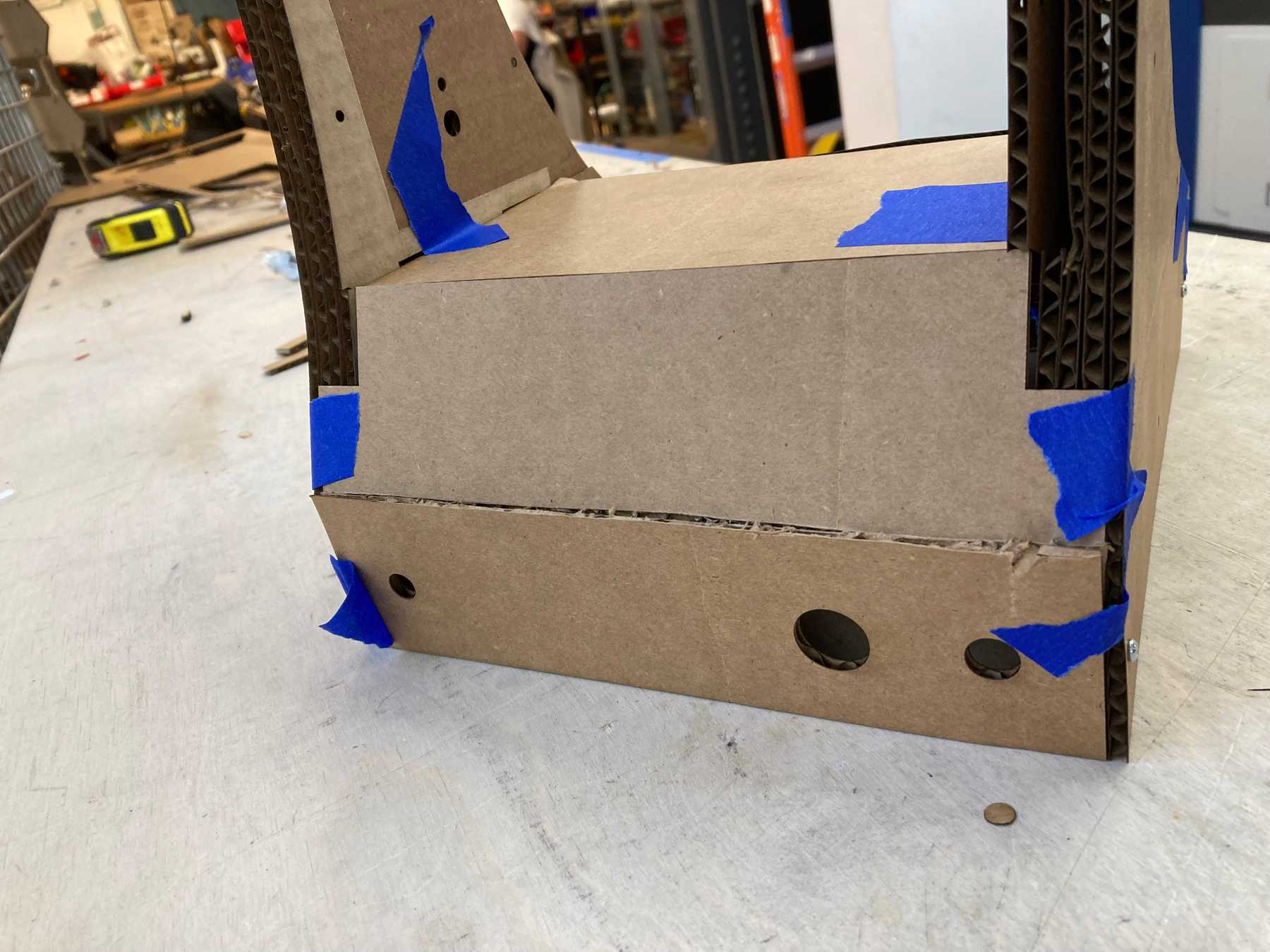
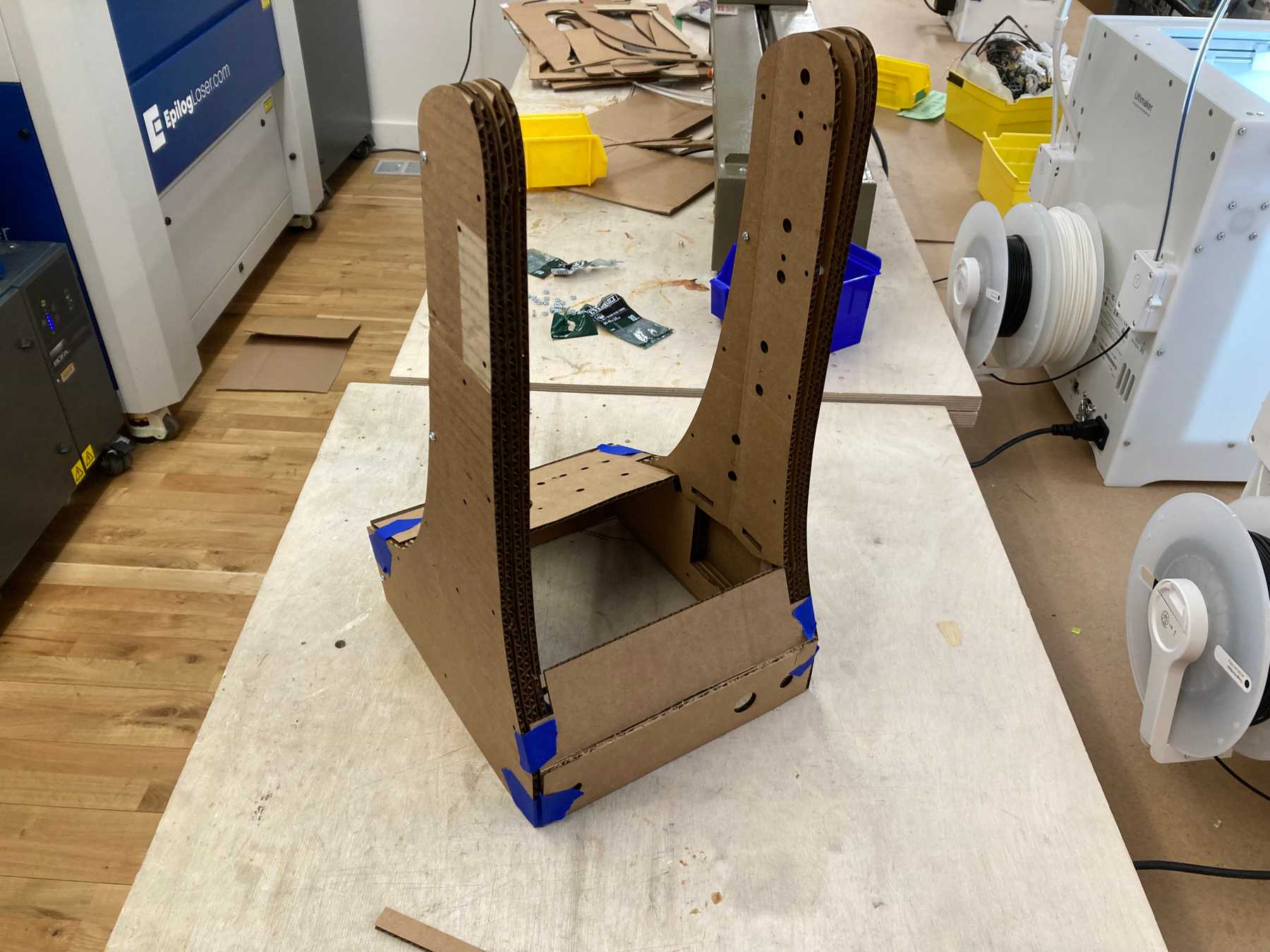 The assembled enclosure — back view
The one mistake I noticed with the cardboard prototype is that I had reversed the PCBs in the design — the holes for the encoders were closer to the back than the front. Switching this allowed the PCBs to fit and also made the design better by allowing more room for the cables and the interactive pieces to be closer to the user.
Adding the Electronics
I could now add the electronics and see if everything worked. For more details on this, see the PCB development post.
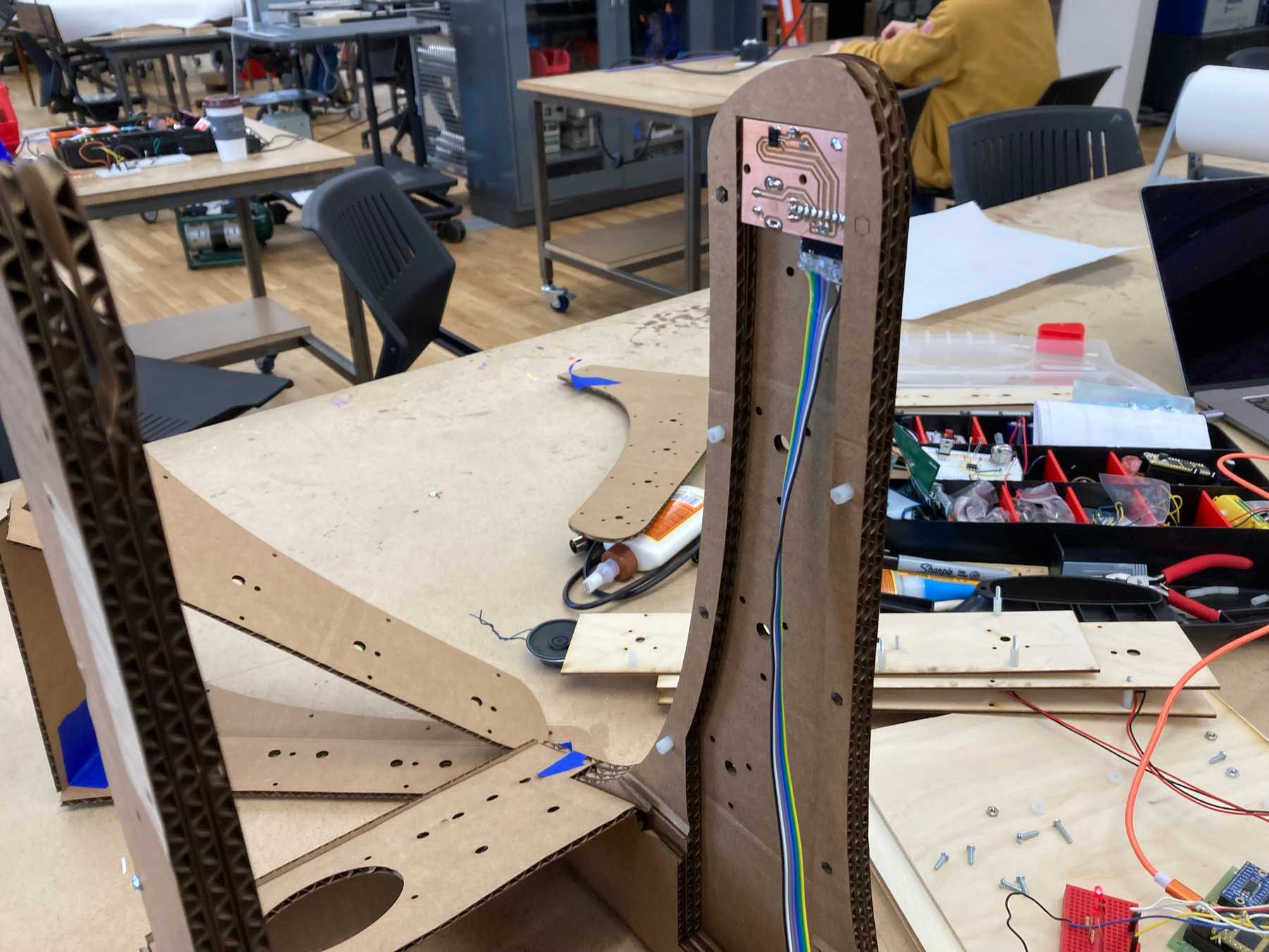 Attaching the first PCB to the inner wall
Testing the electronics: Distance, rotation, and encoder
Testing with two rods
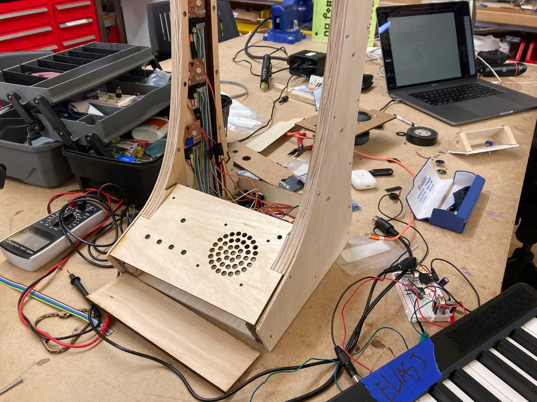
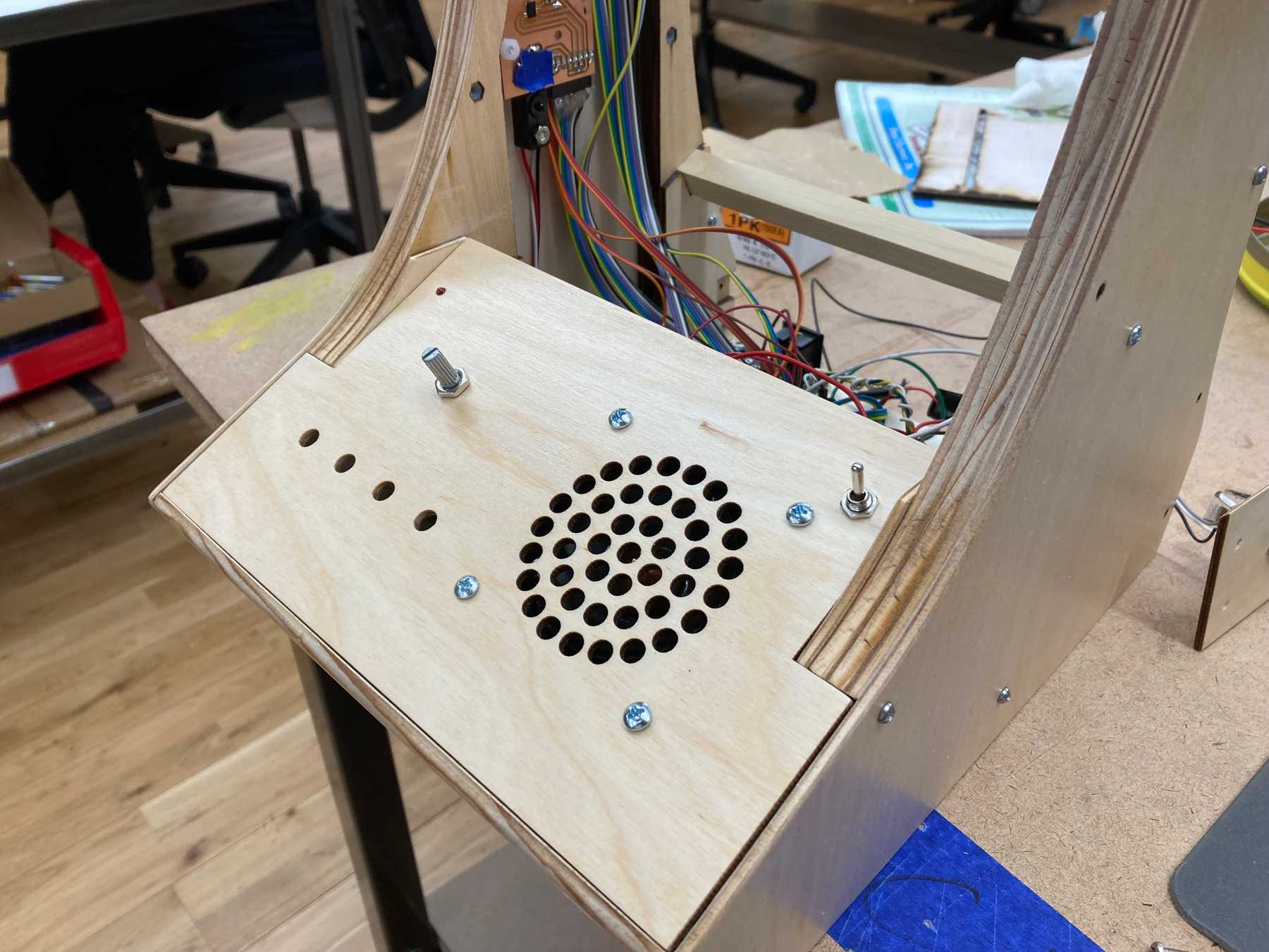
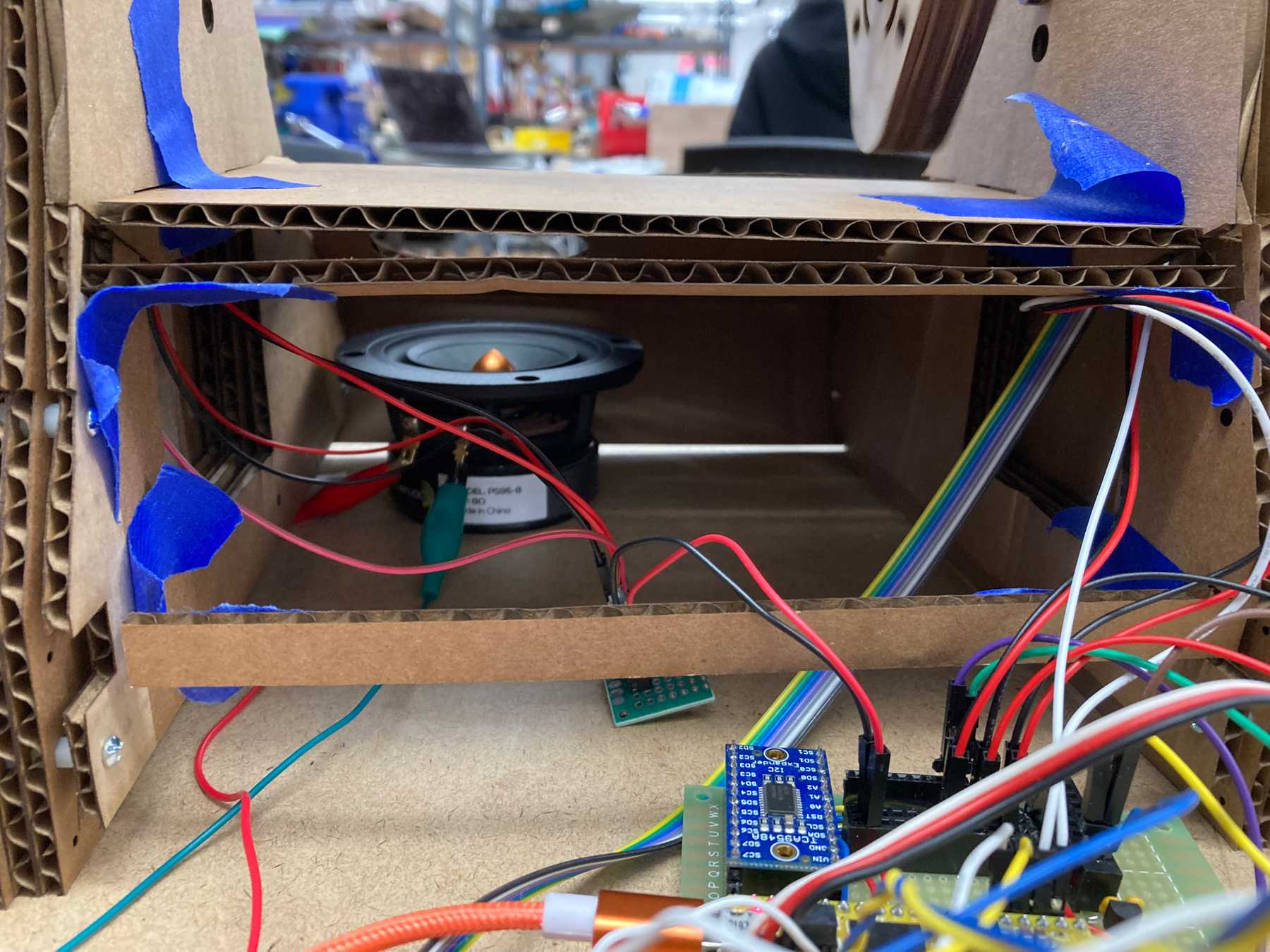 Connecting the wires and the speaker
More testing
Final Wooden Version
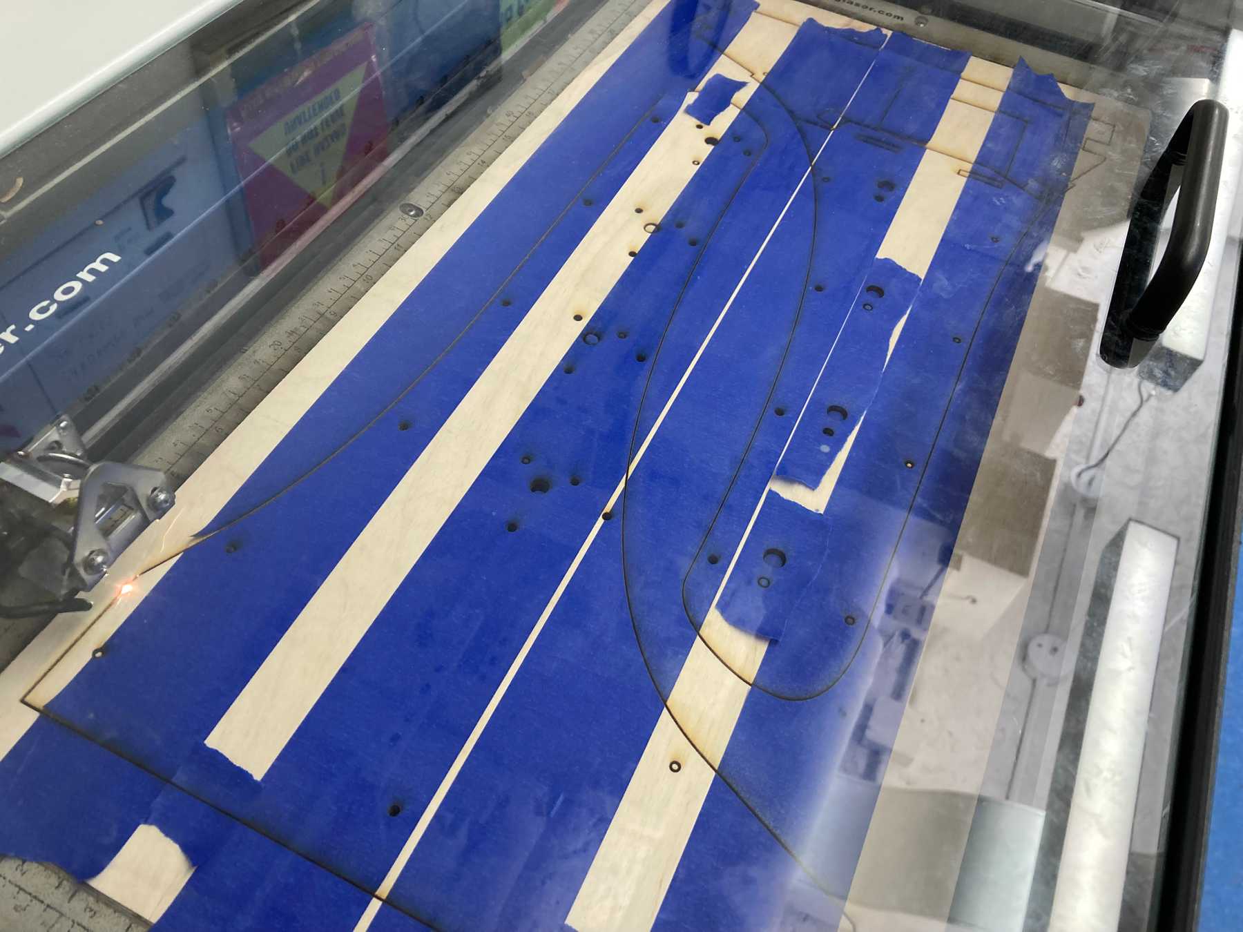
Now that I was confident in the design, it was time to cut the wood. I taped over it to minimize burn marks.
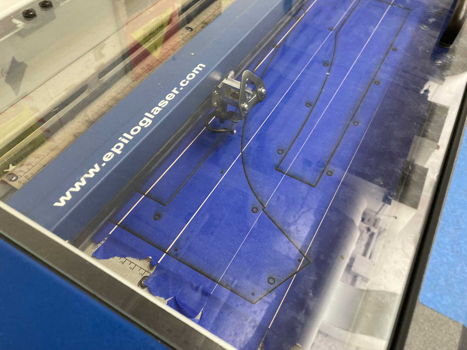 The inner pieces on thicker wood
The plastic standoffs fit into hexagonal holes in the inner walls, so that the outer walls could both screw in to the same hole.
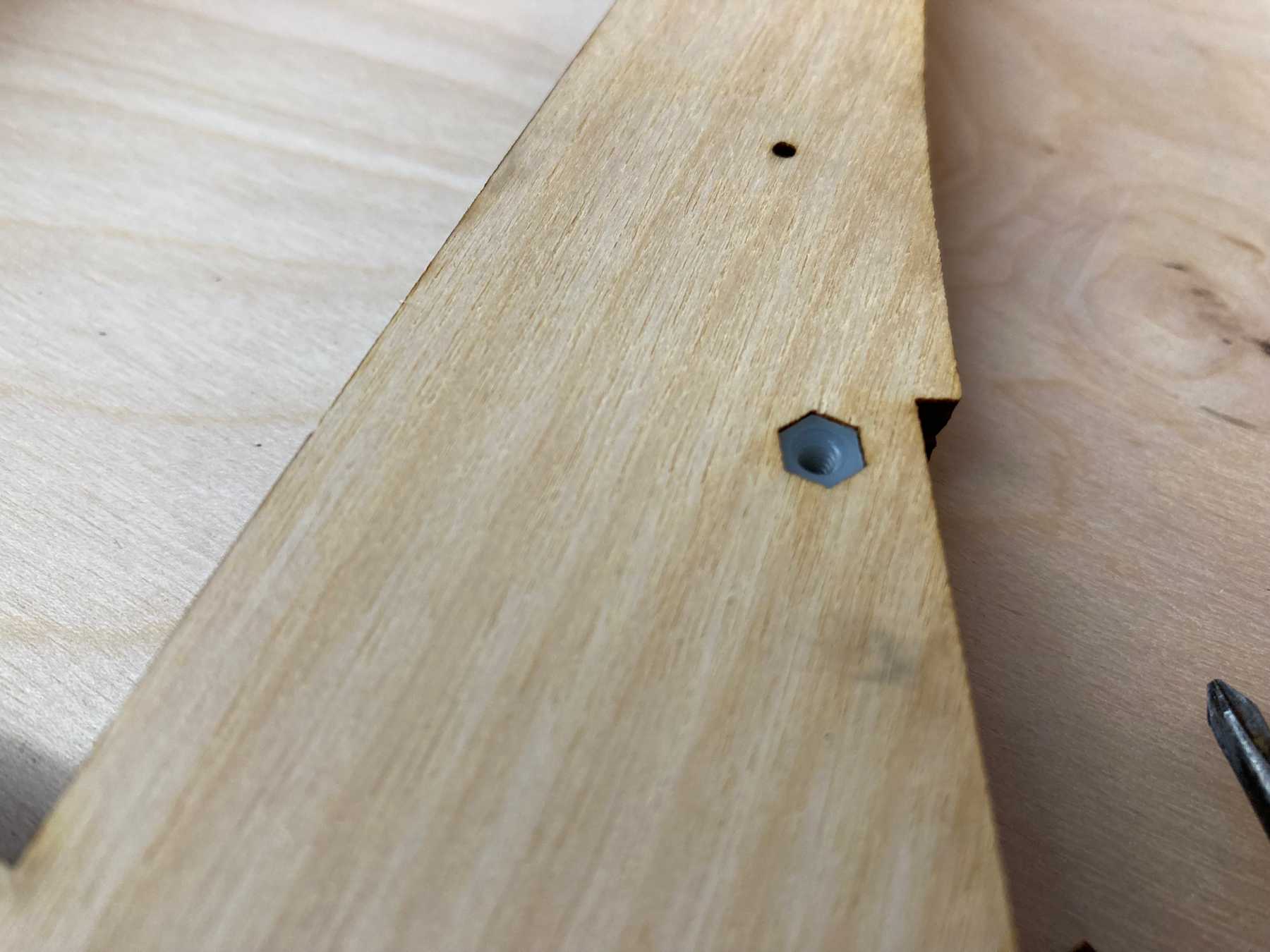 Plastic standoffs fit in the inner pieces
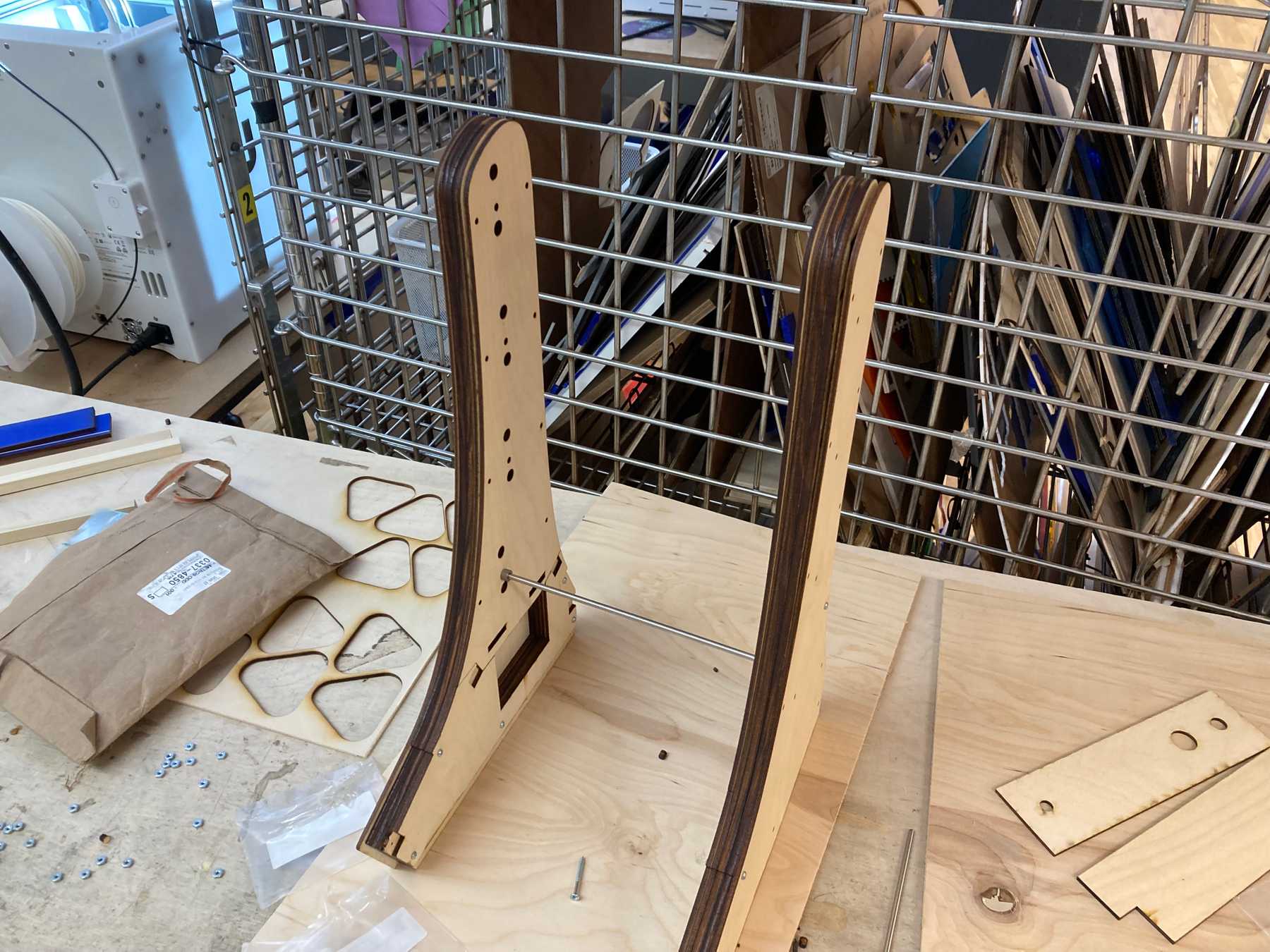
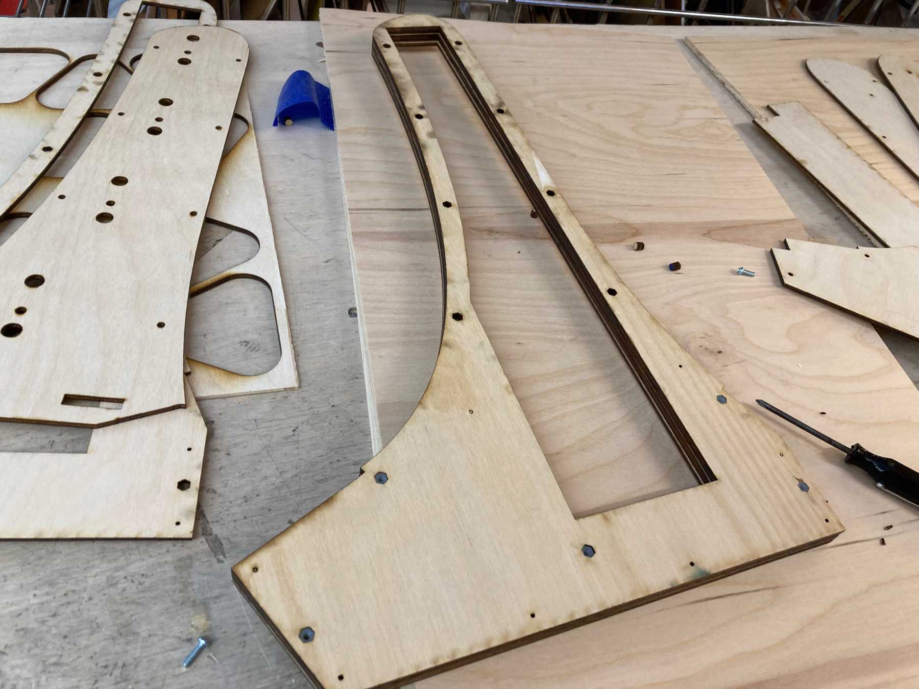 Inner section made up of three layers
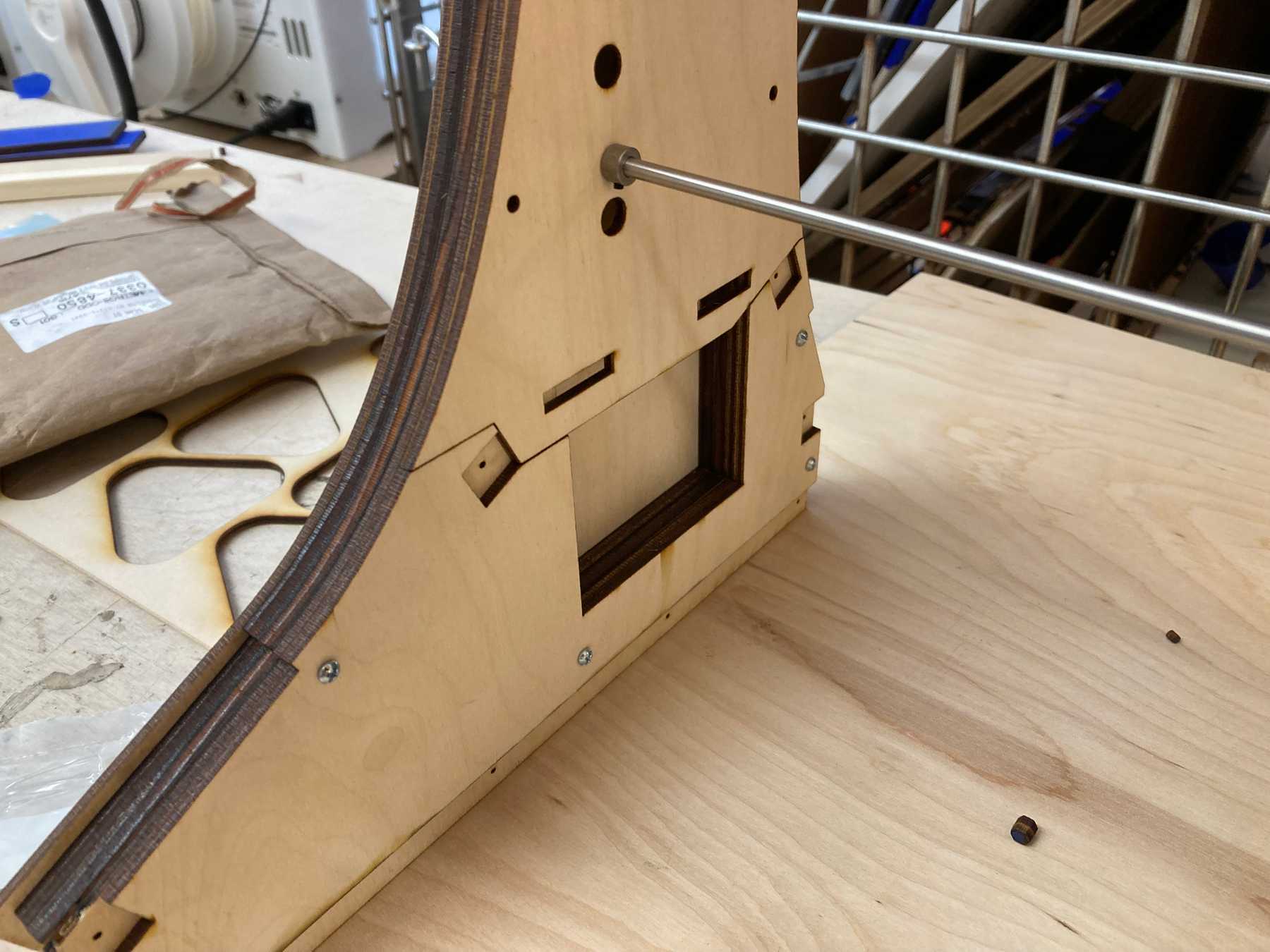 The inner wall — the large hole is for the wires and the small square holes hold the support beams
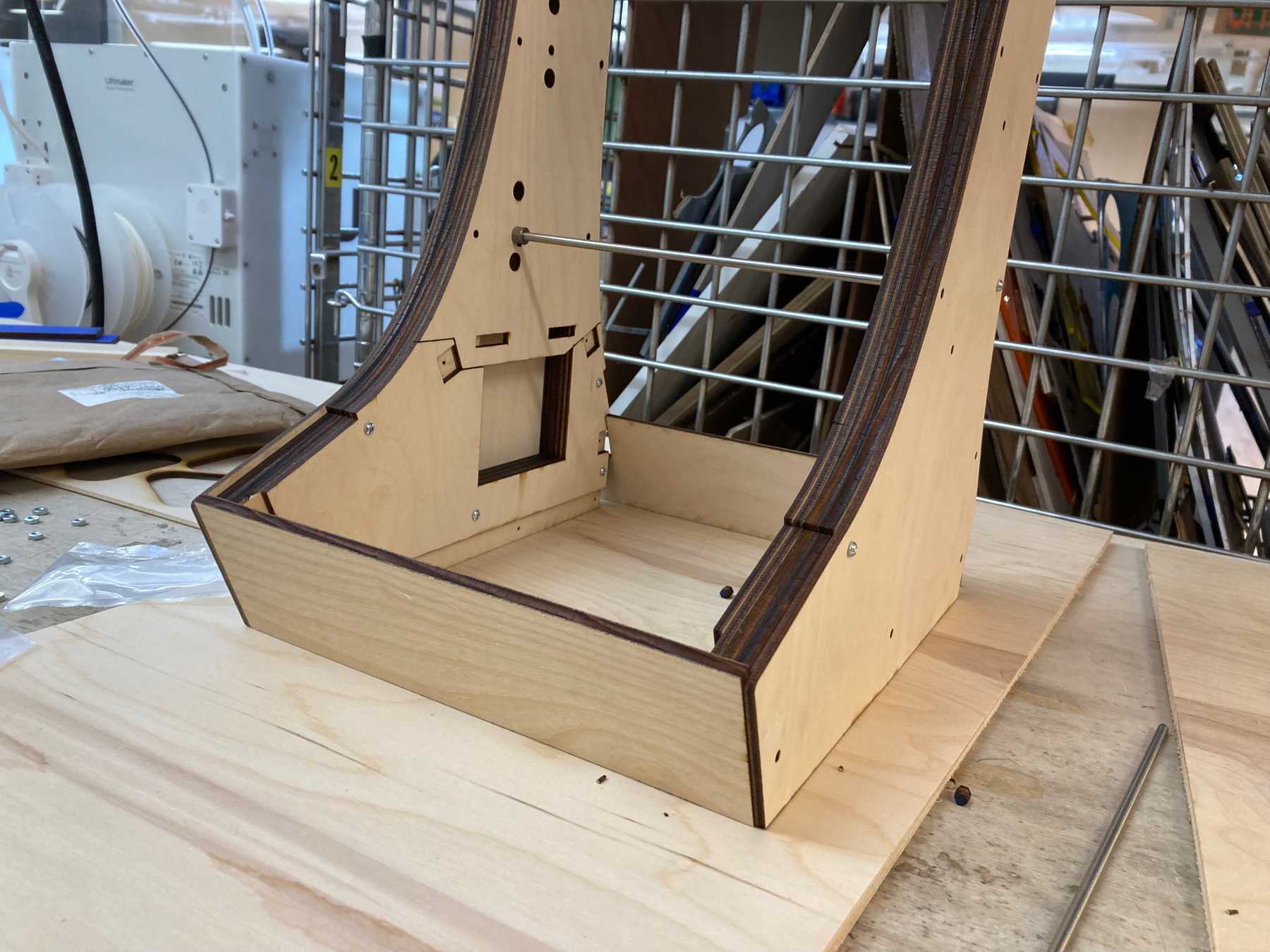 The front panel is cut out of the thicker wood to allow for a more rounded sanded edge (after sanding)
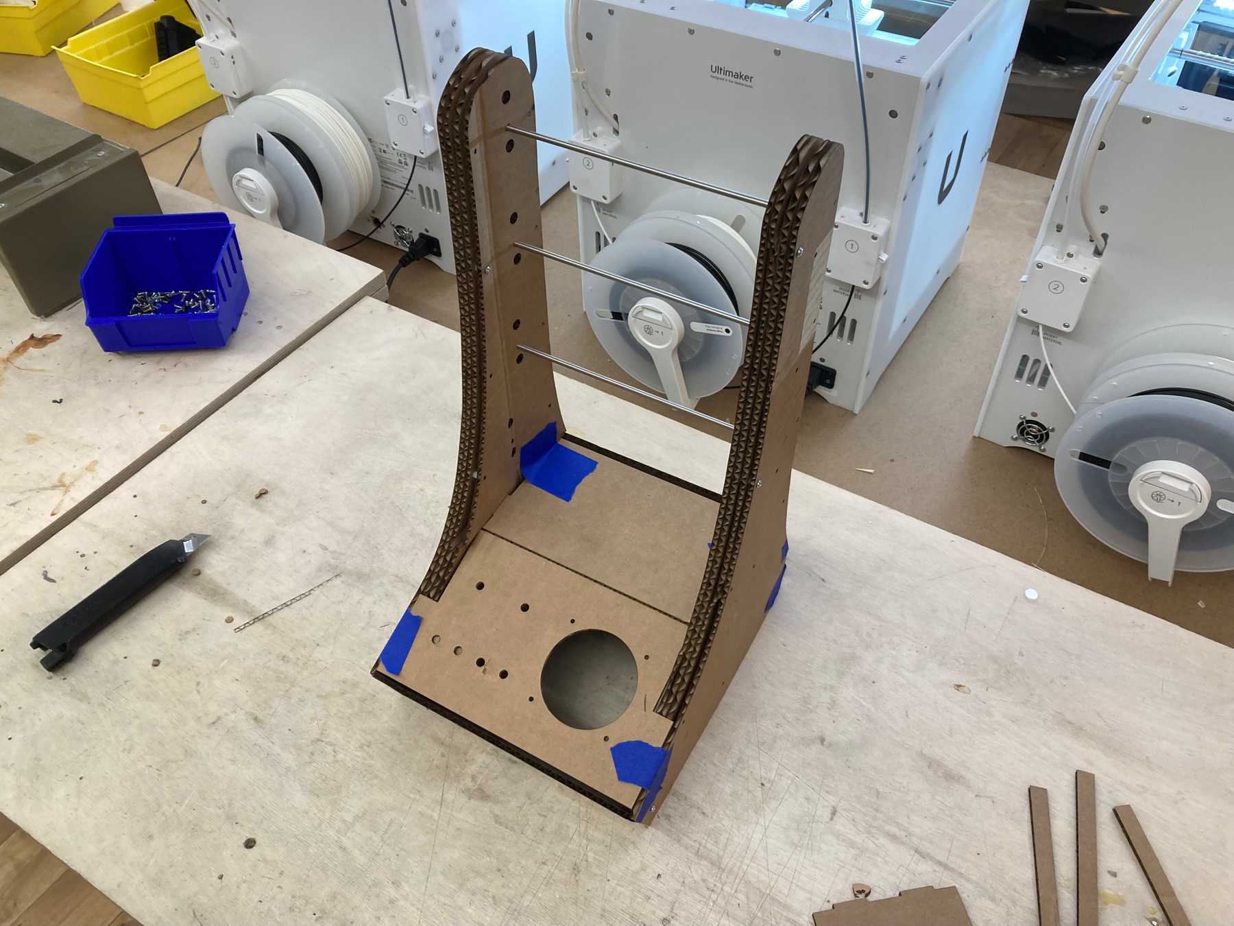
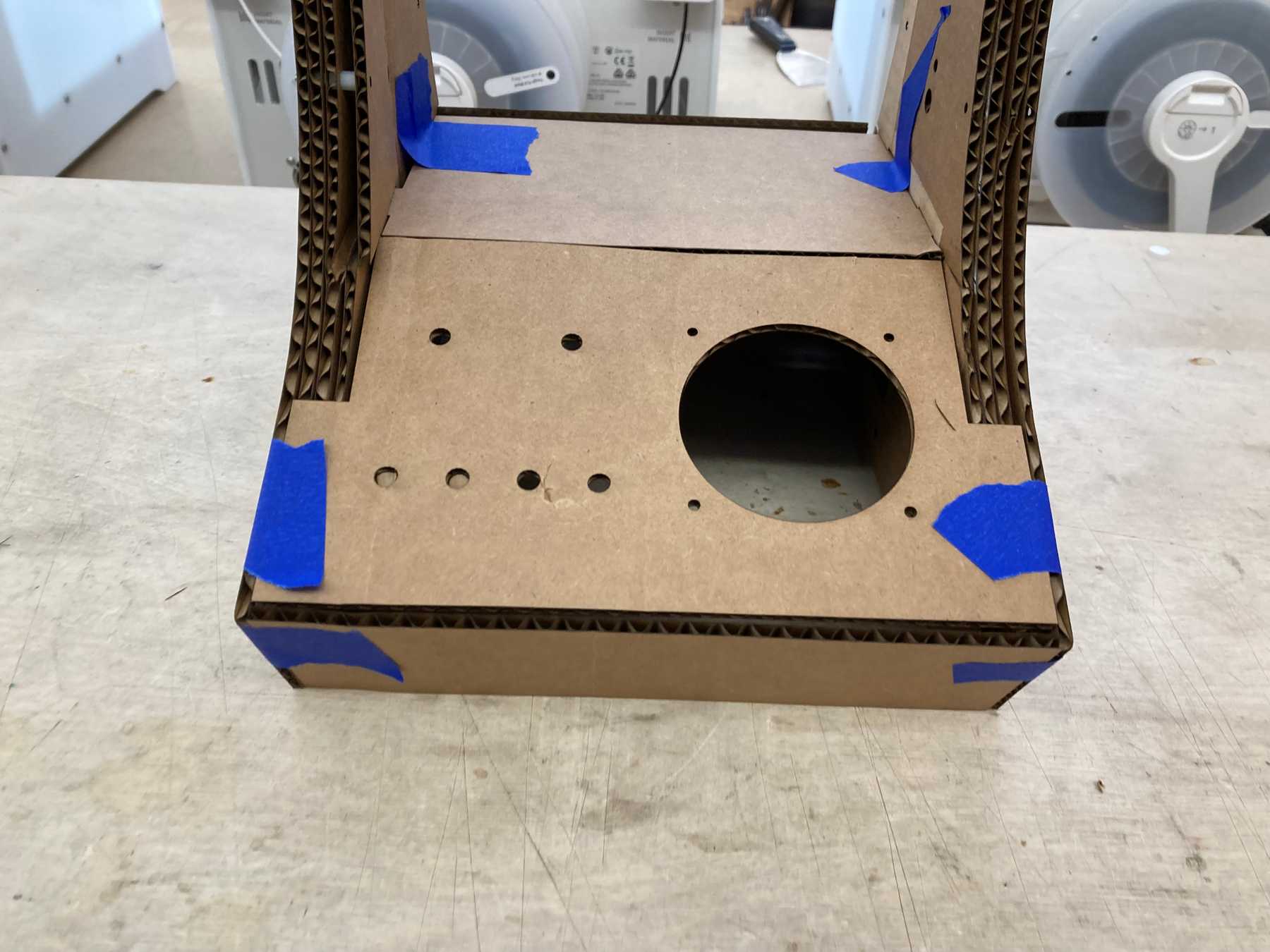
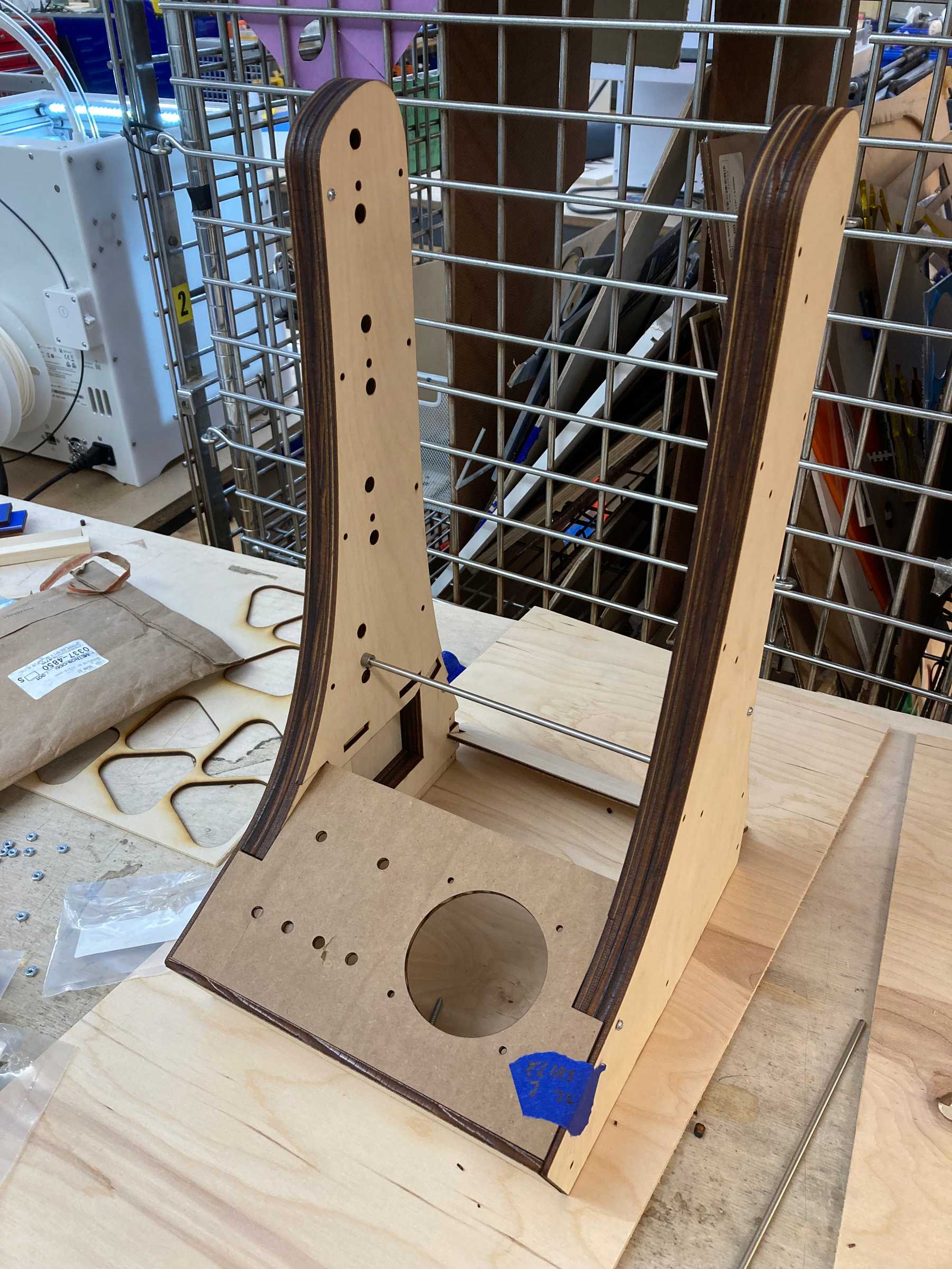 I wasn’t yet set on the front panel design so used the cardboard
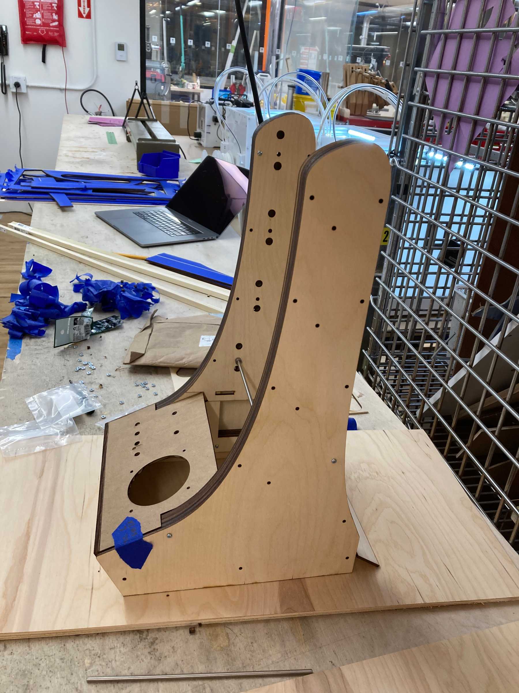 Side view with the front panel
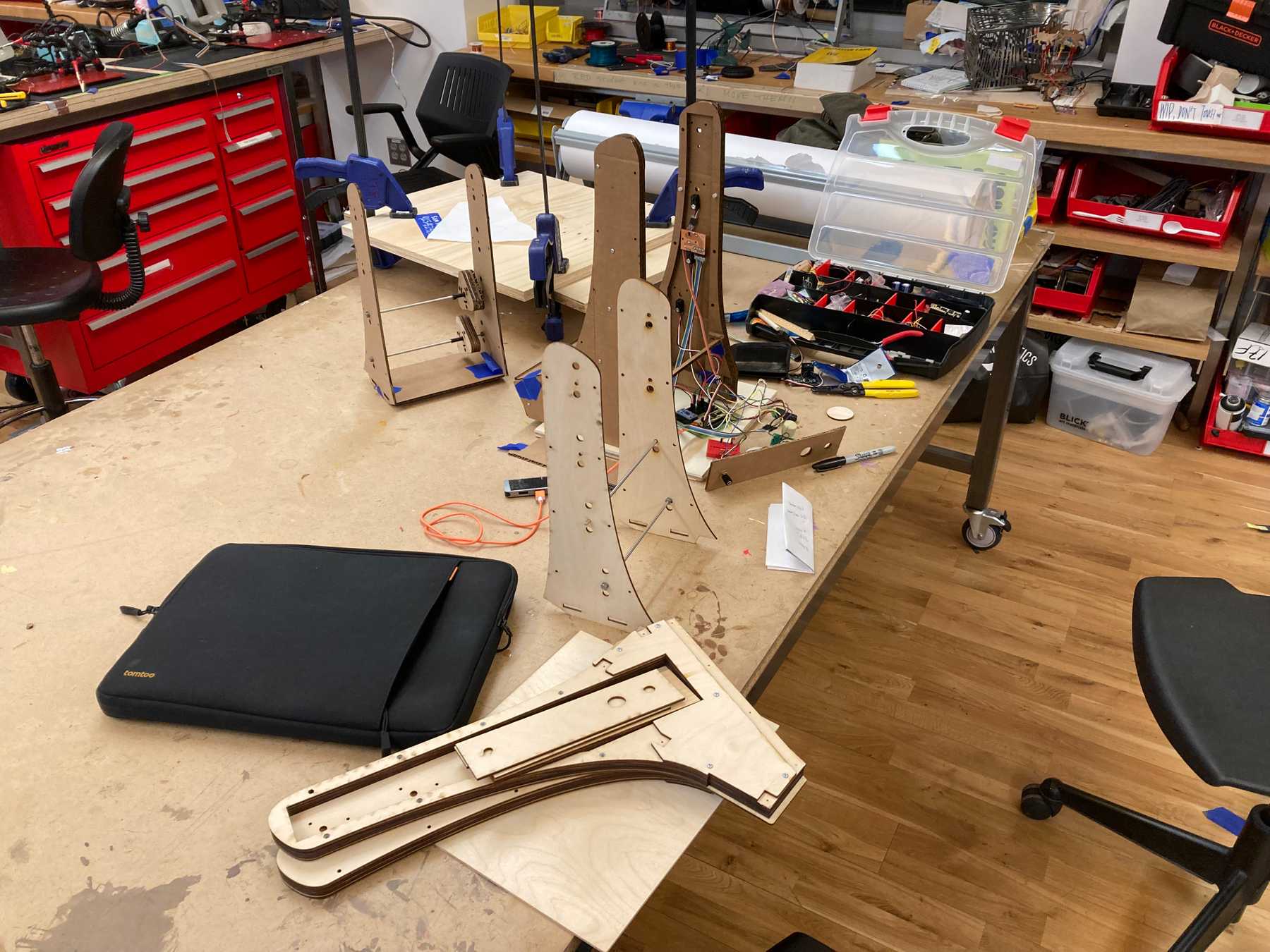 Assembling the removable inner section
Drilling it all Together
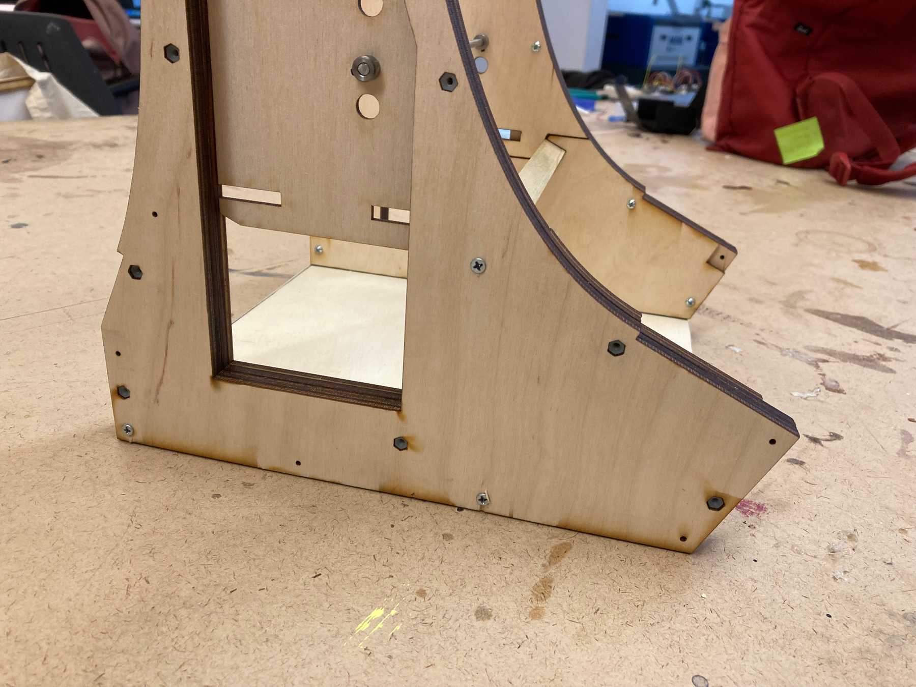
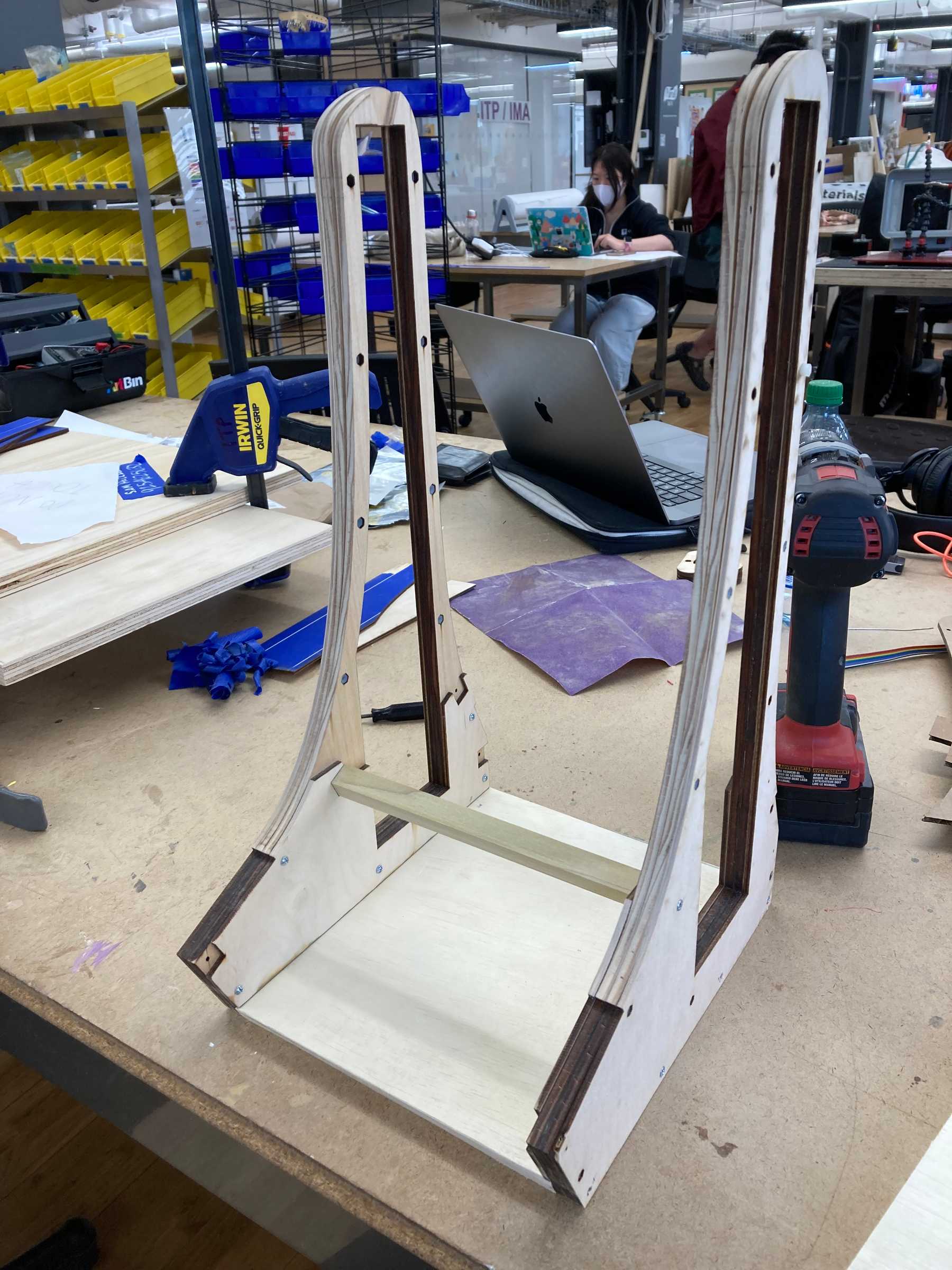
The inner walls are screwed to the base and the 1/2” dowel support rods. These screws are covered up by the outer wall.
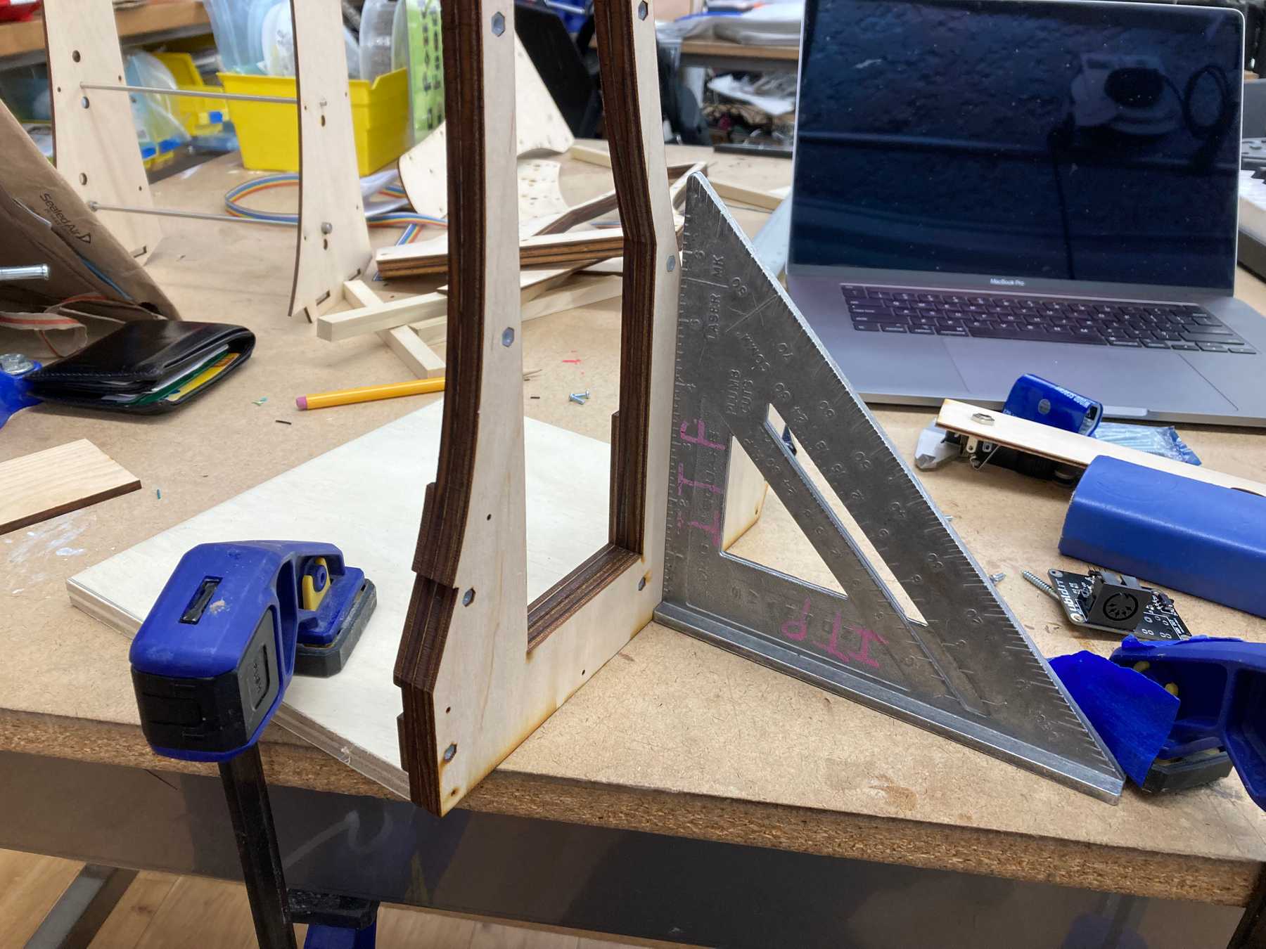 Drilling the walls to the base
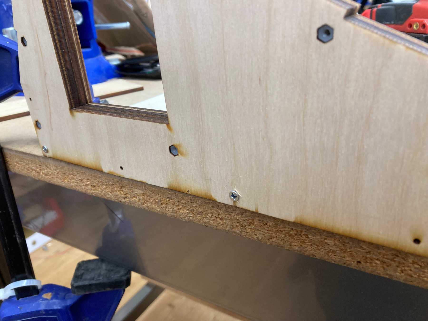 Using the laser cut pilot holes
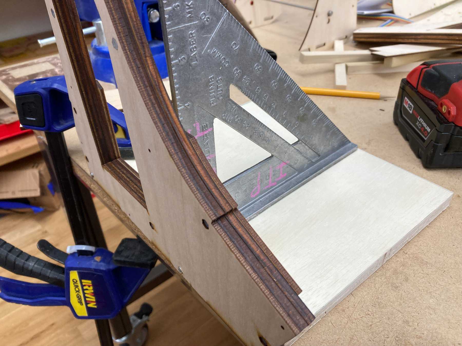 Making sure the angle was square
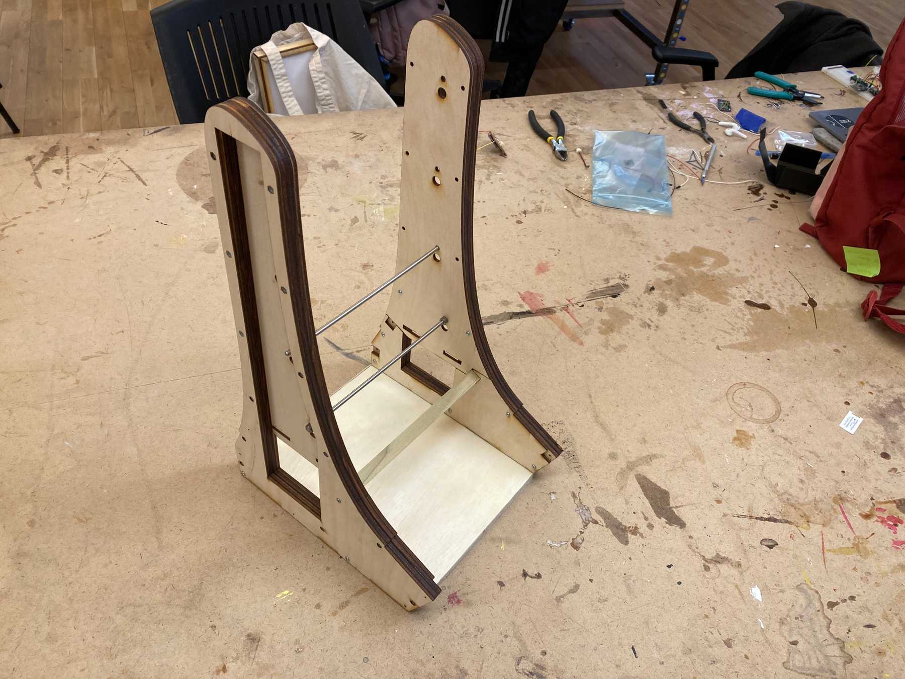 The structure connected by the base and square dowel
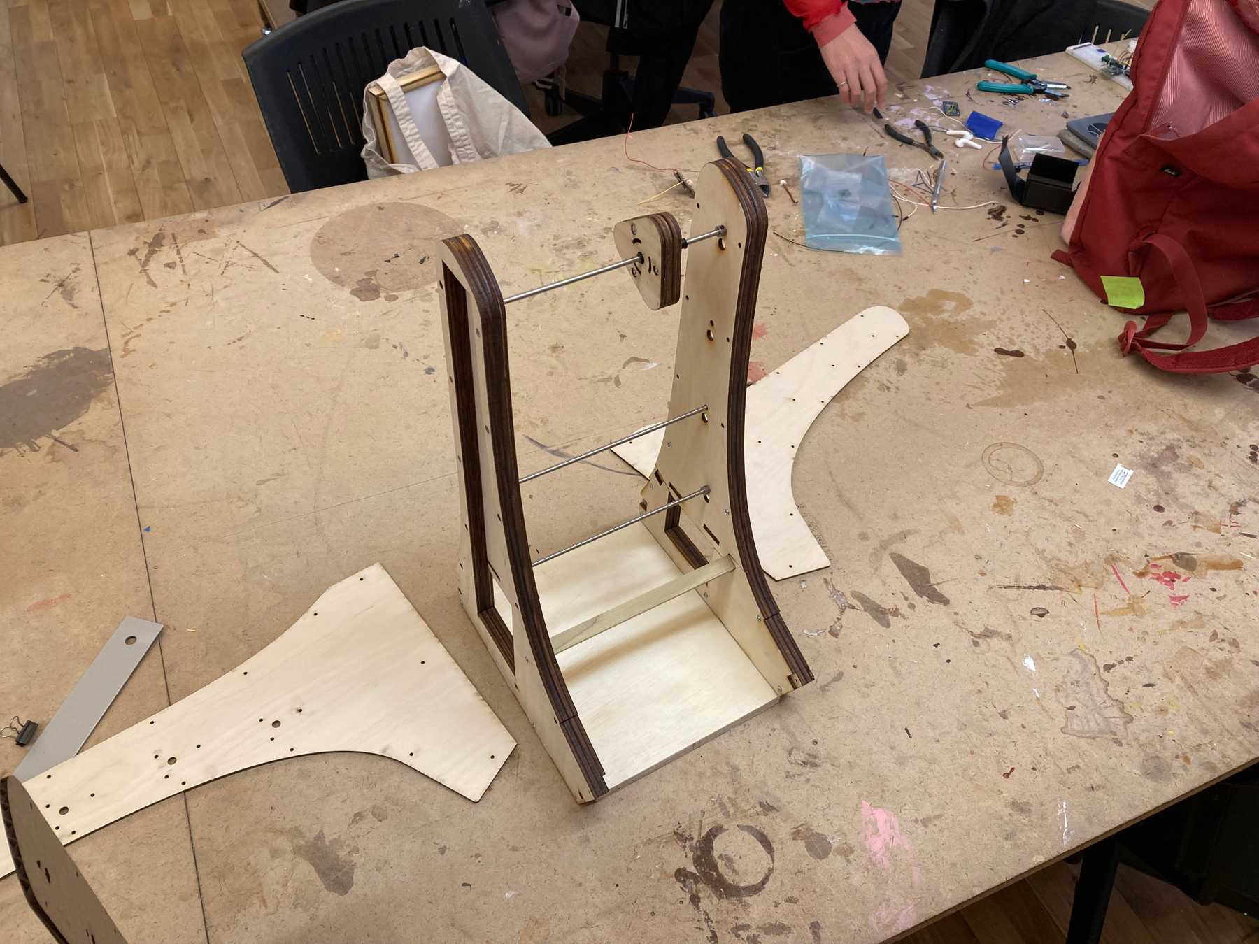 The outer walls would cover up the screws
Moving/Spinning is much more firm than with the cardboard prototype
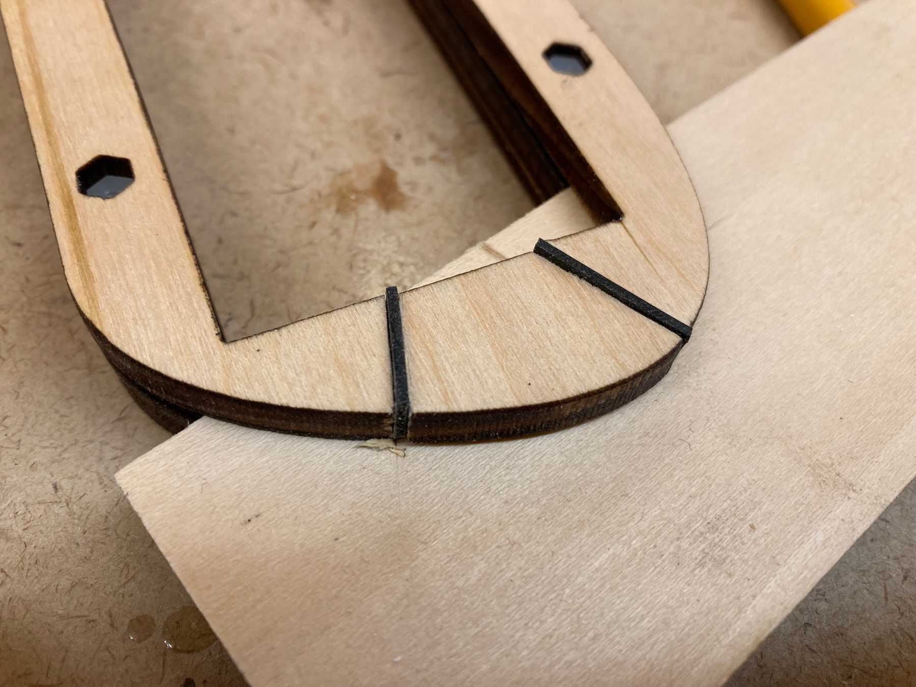
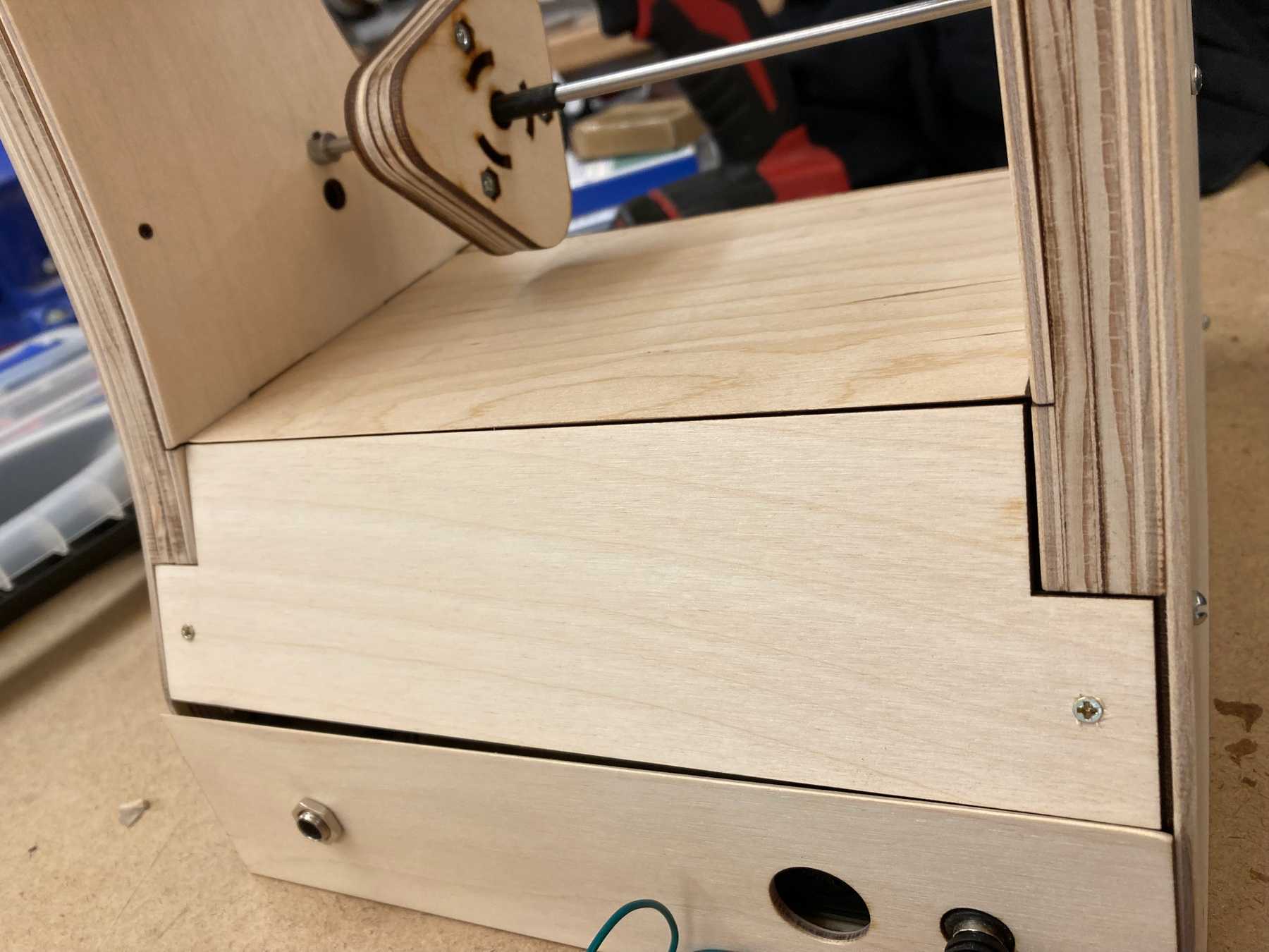
One quirk of the design is that the shaft collars holding the rods in place make it a bit difficult to remove the inner section. I had to cut out a slot in the top and glue it to the inner piece so that you could slide out the entire section.
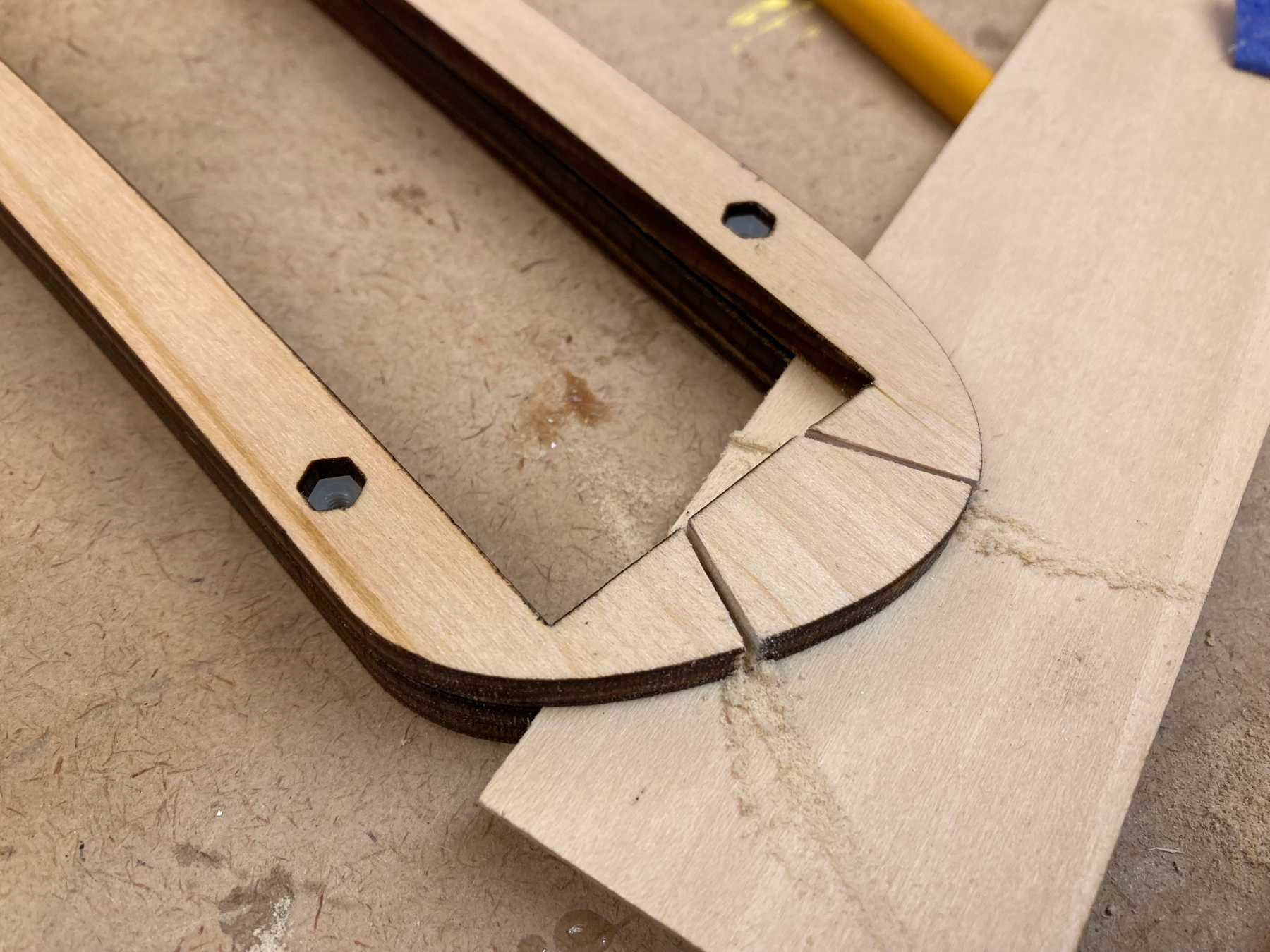 Cutting slots in the inner wall
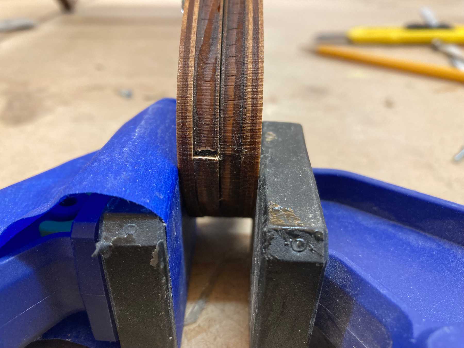 Glueing the cutout piece to the removable section
Removing the inner section
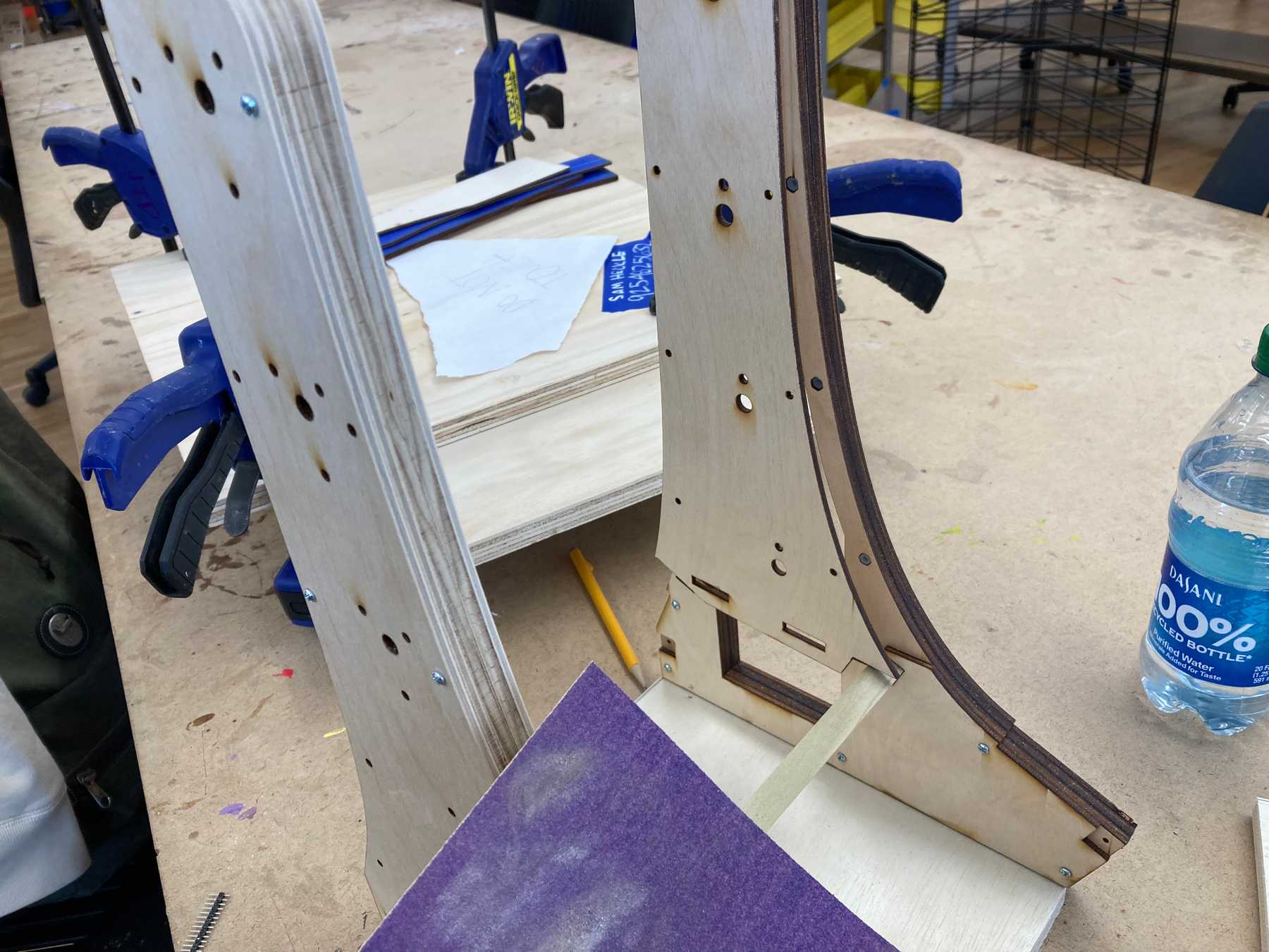
Sanding
I sanded the visible edges that were burnt during the laser cutting process. This revealed the wood grain and made the surface smooth to the touch.
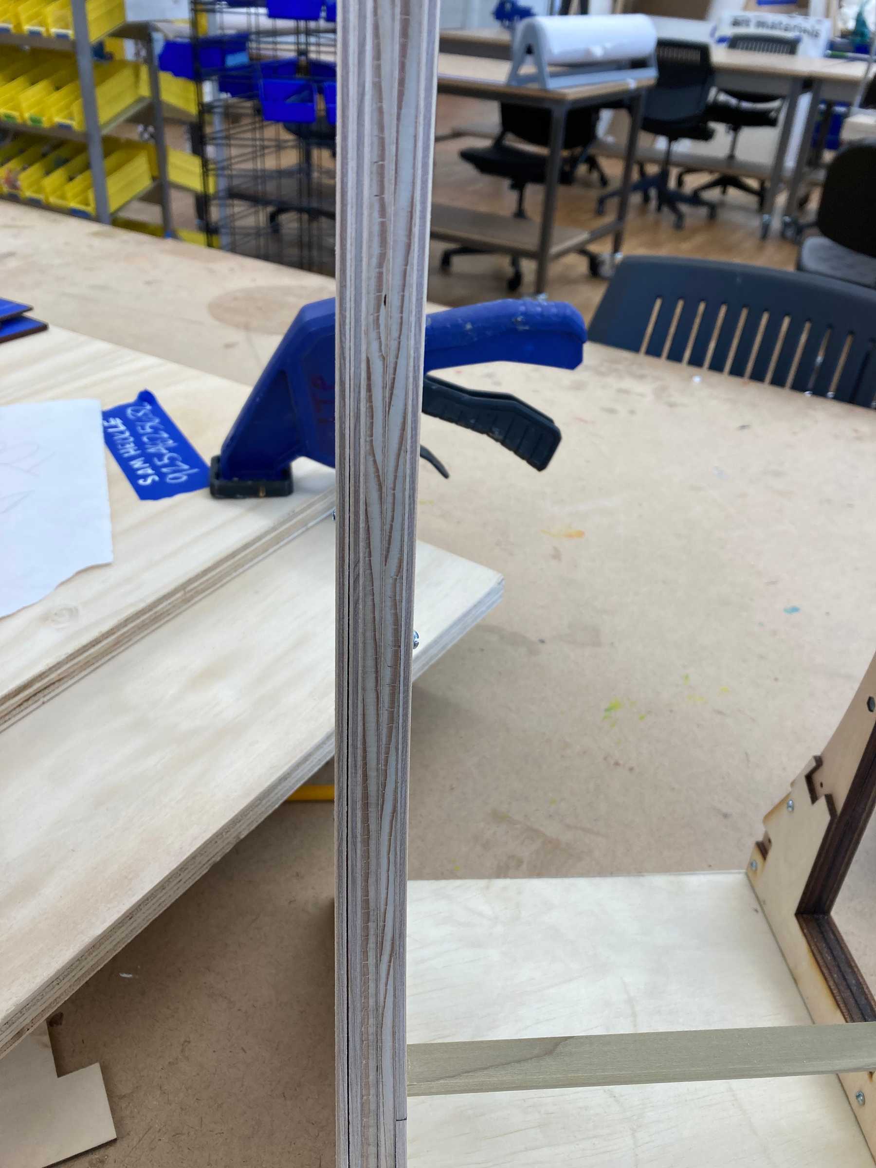 Looks and feels much better sanded
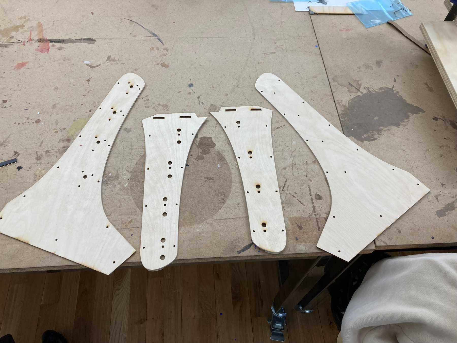 Sanding the outer-facing panels
Final Assembly
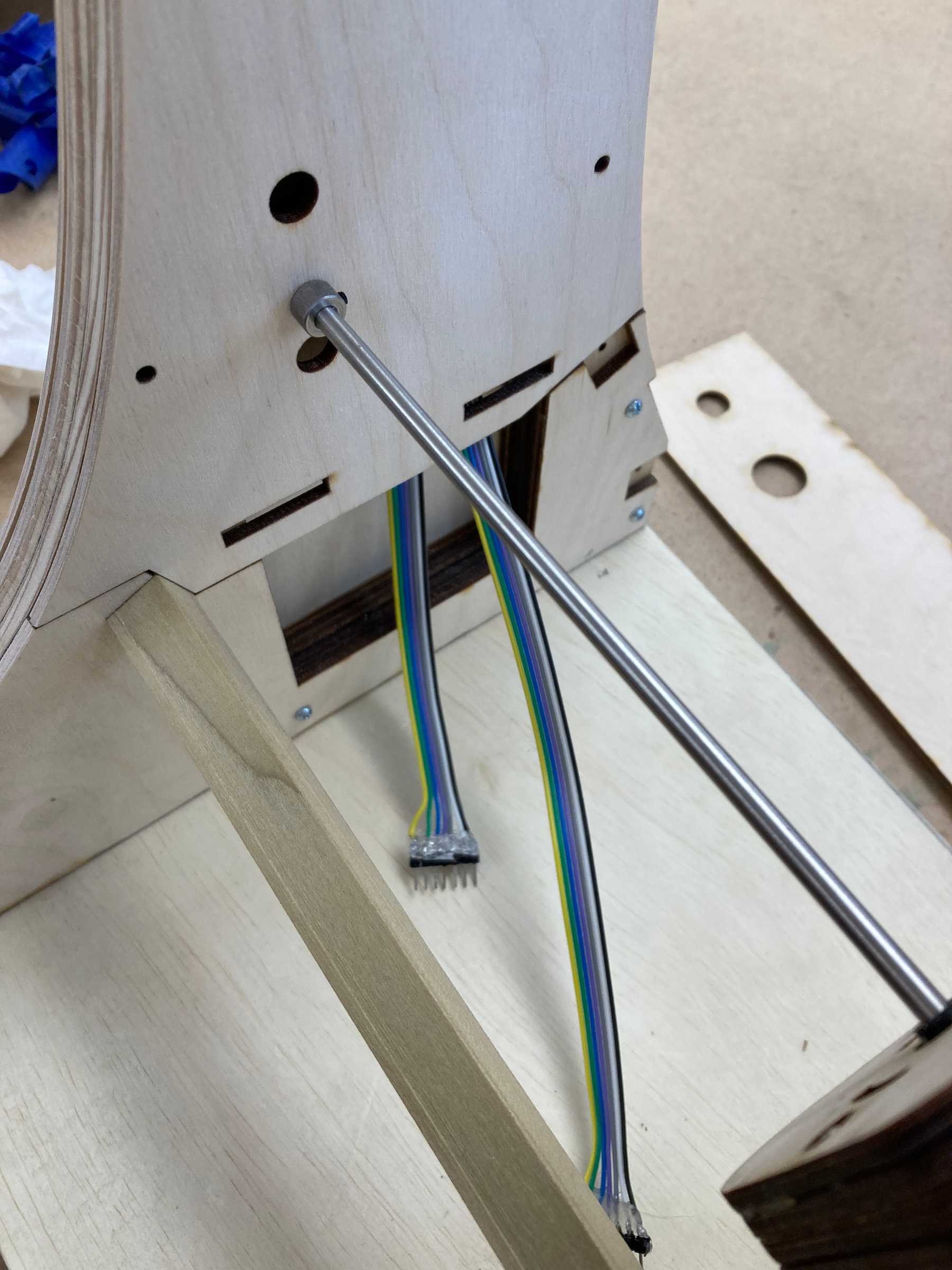 Ribbon cables from the sensors
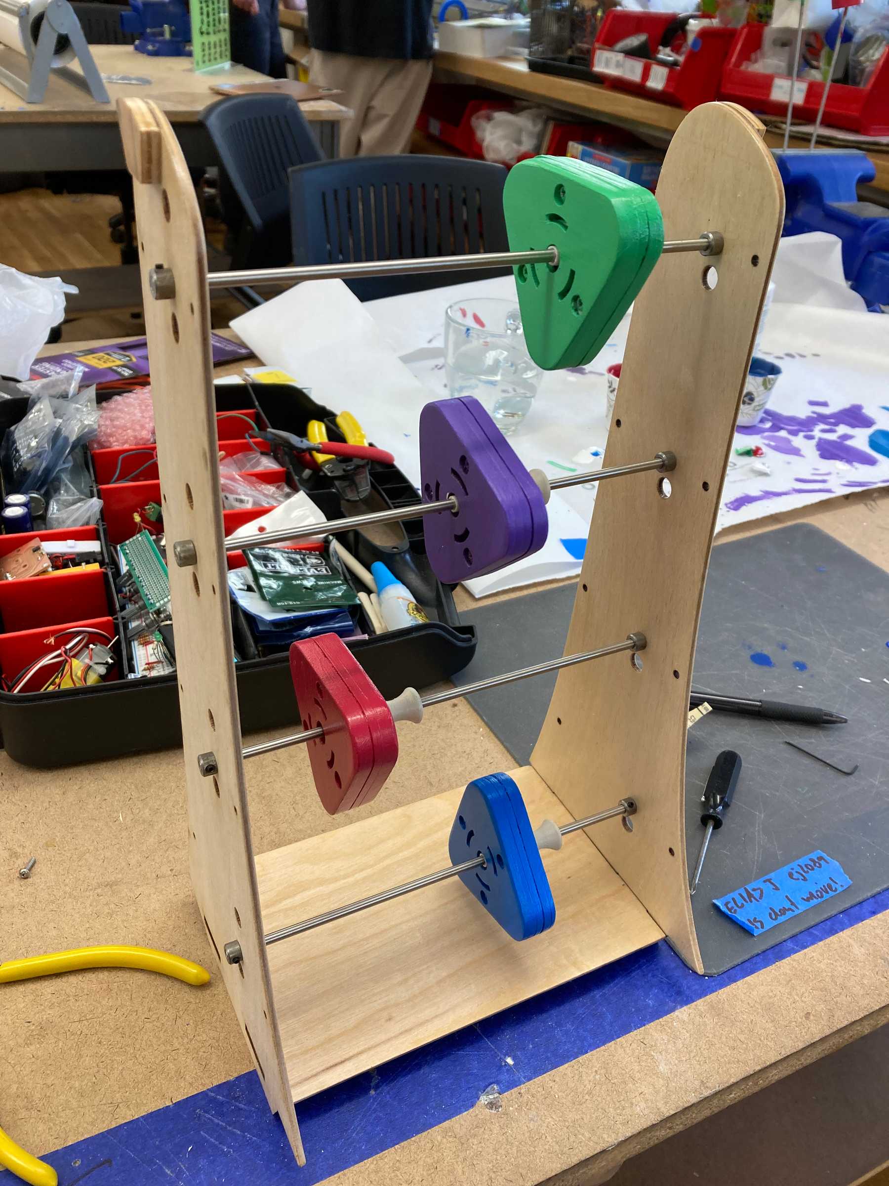
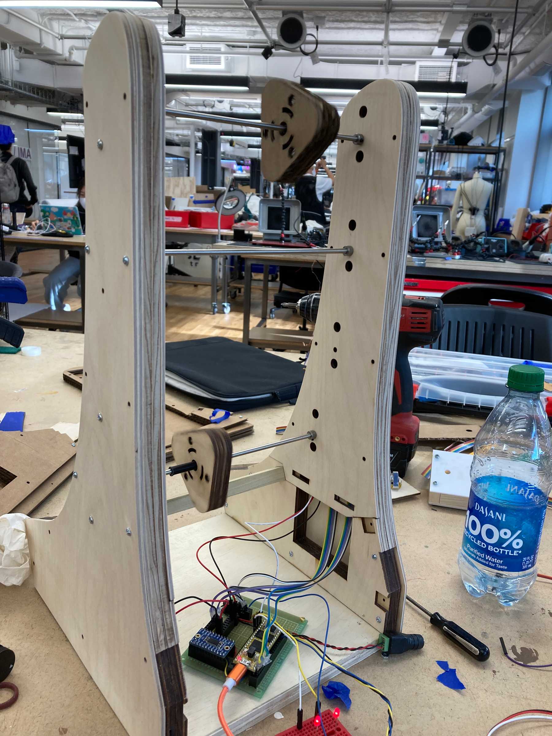 Adding the spinners to test if everything works
Testing the build
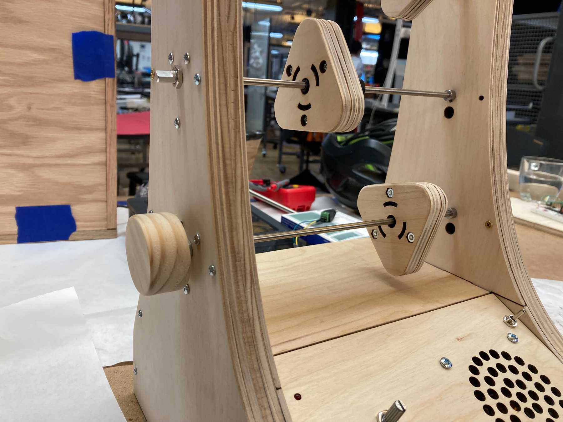
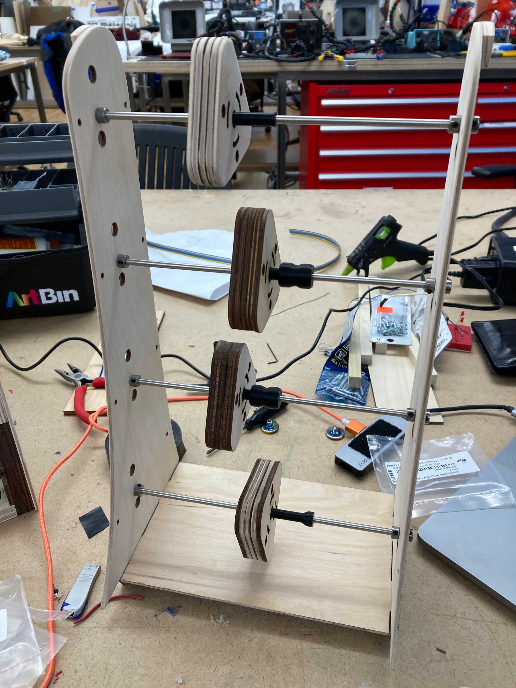 All four spinners attached to the inner section
All four rods working!
Testing with the speaker mounted
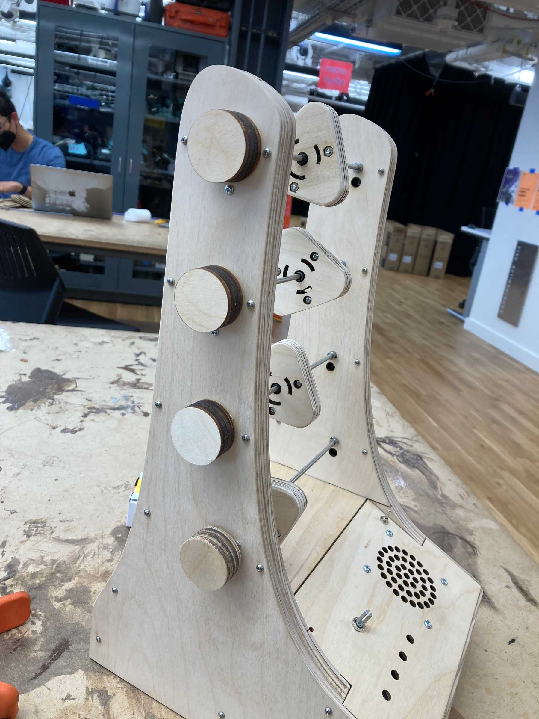
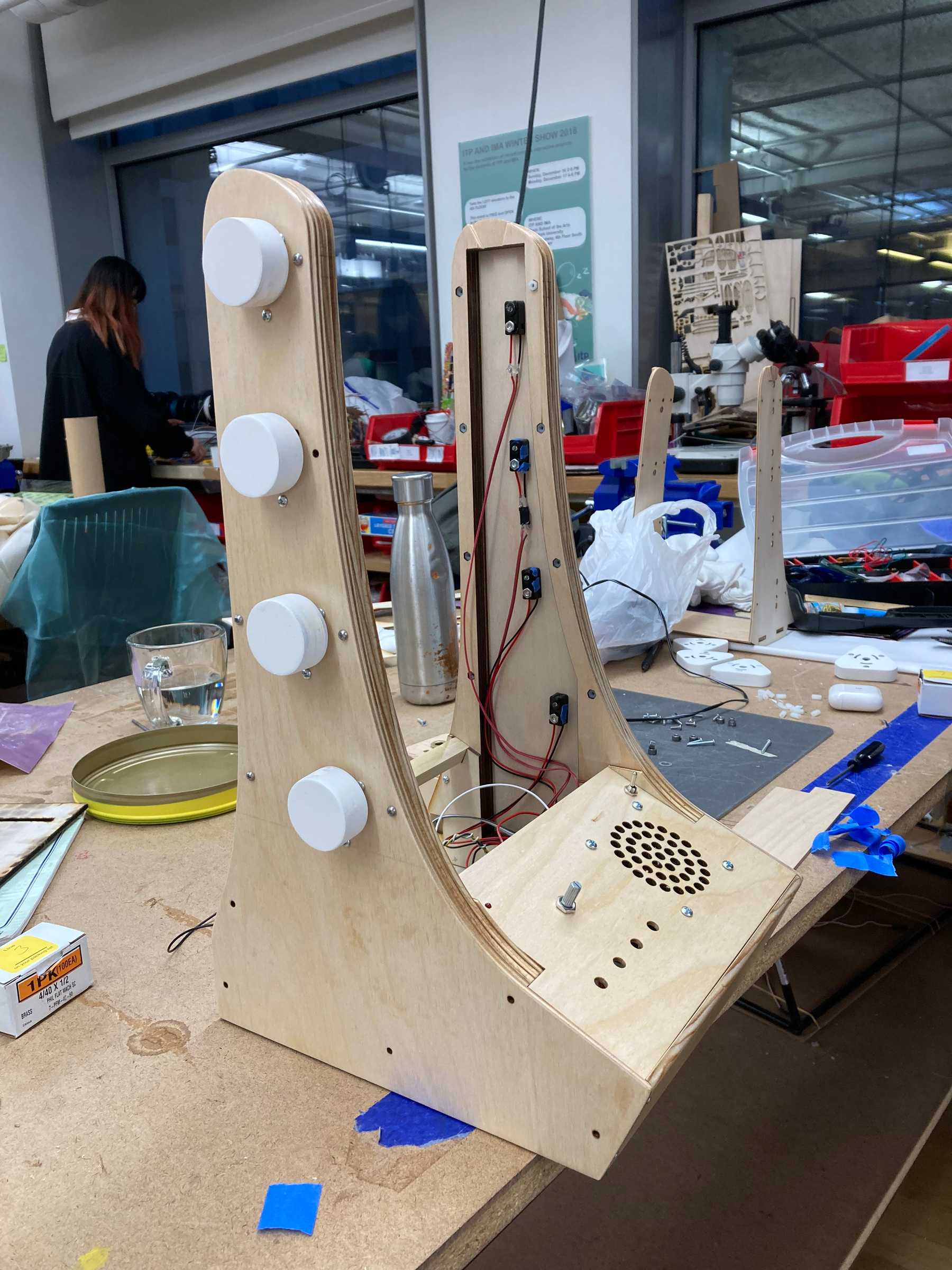
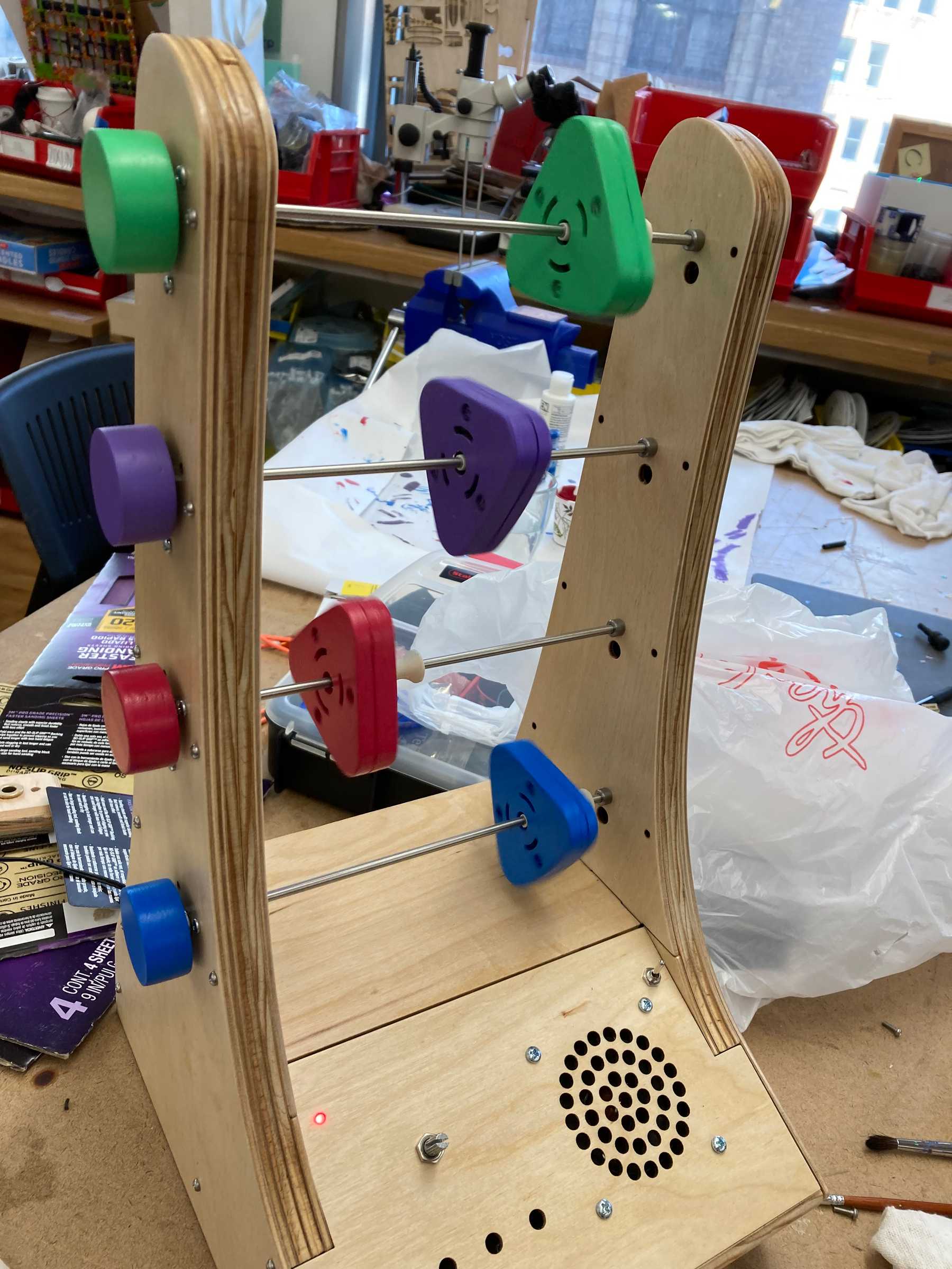
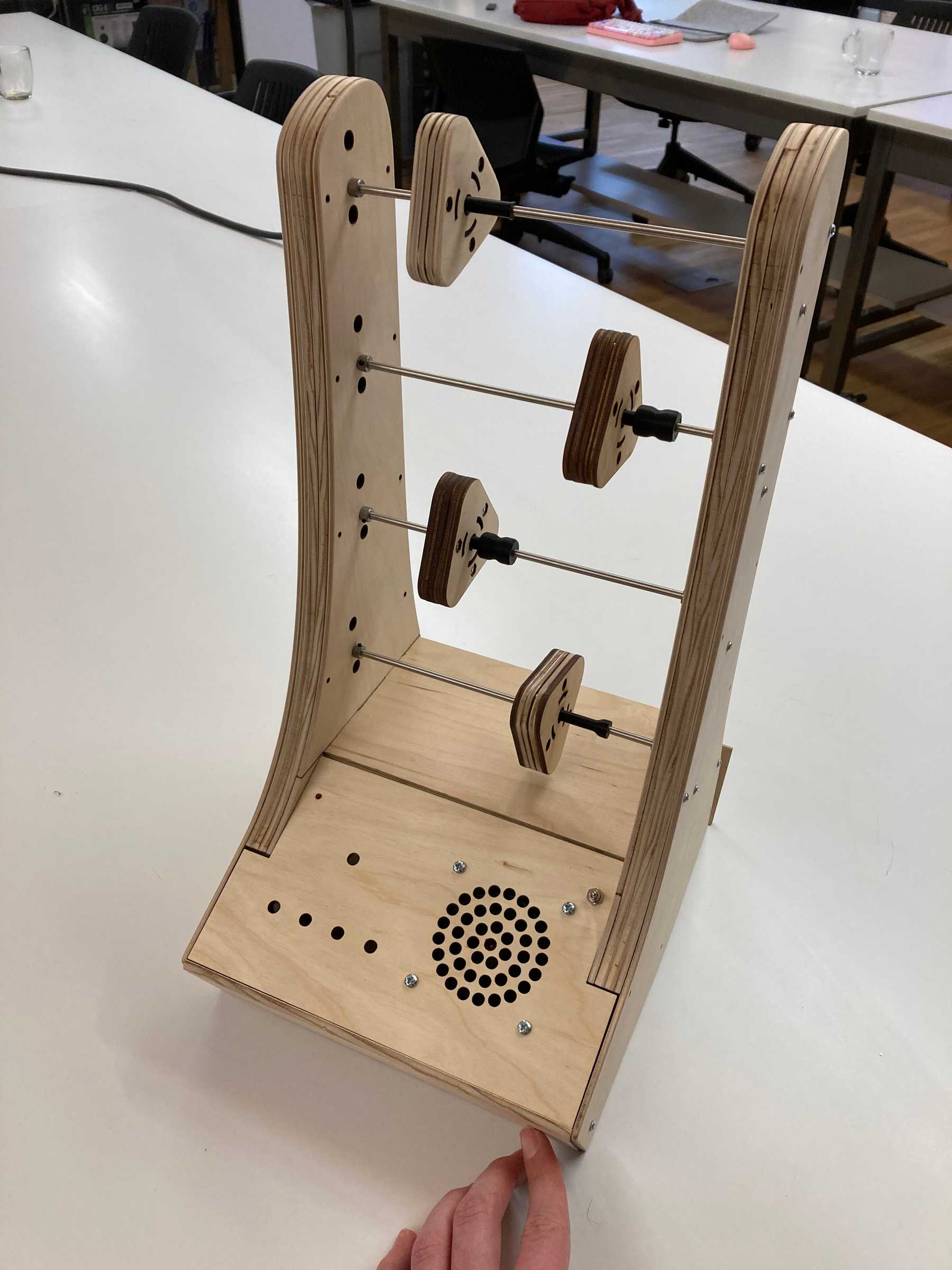 The assembled, working enclosure
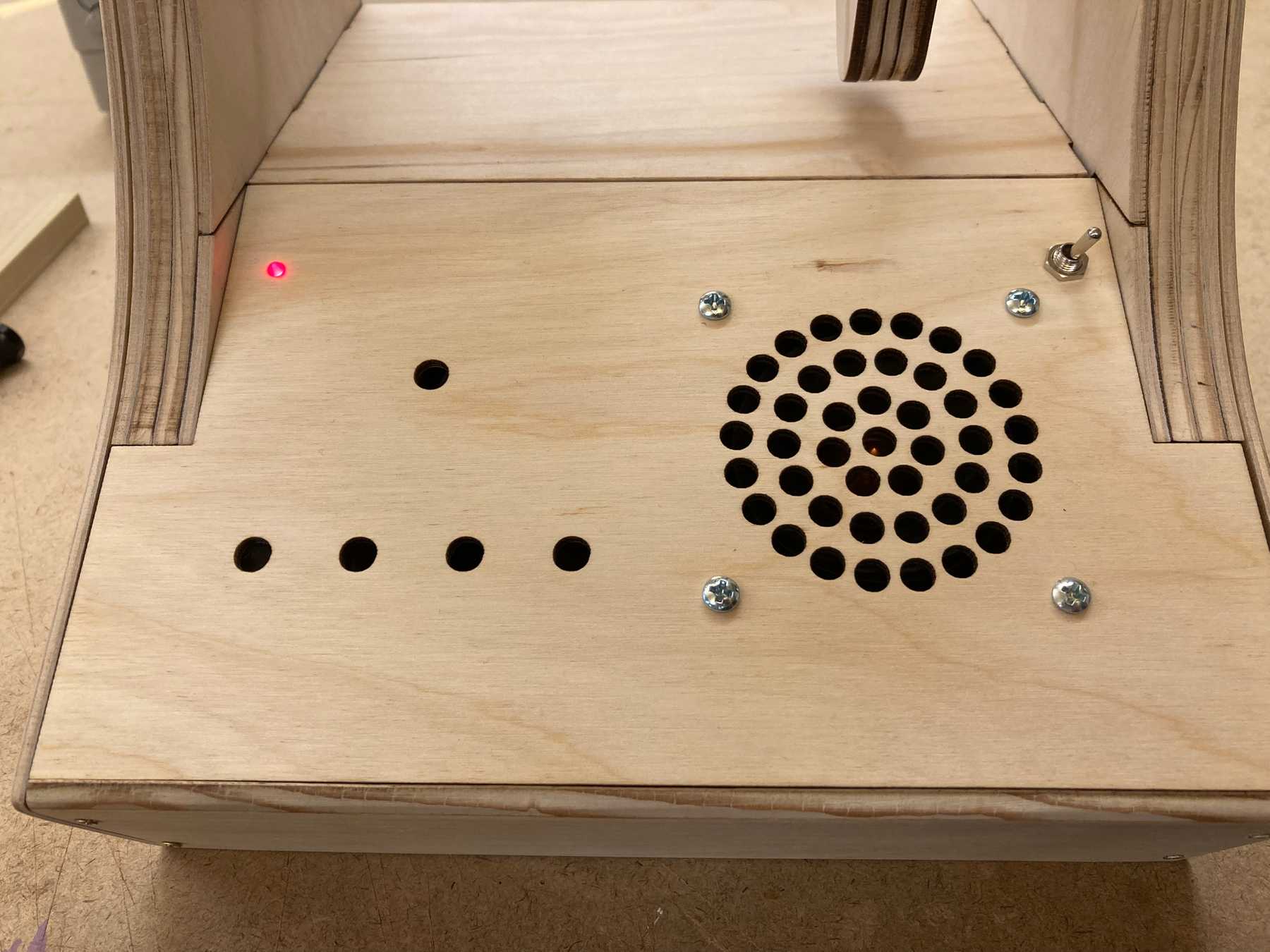
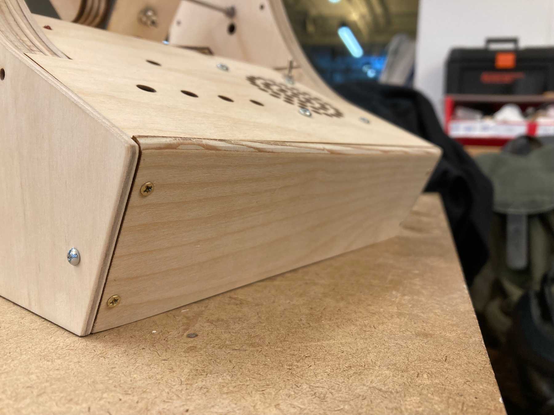 The front face, cut out of the thicker plywood
Encoder Knobs
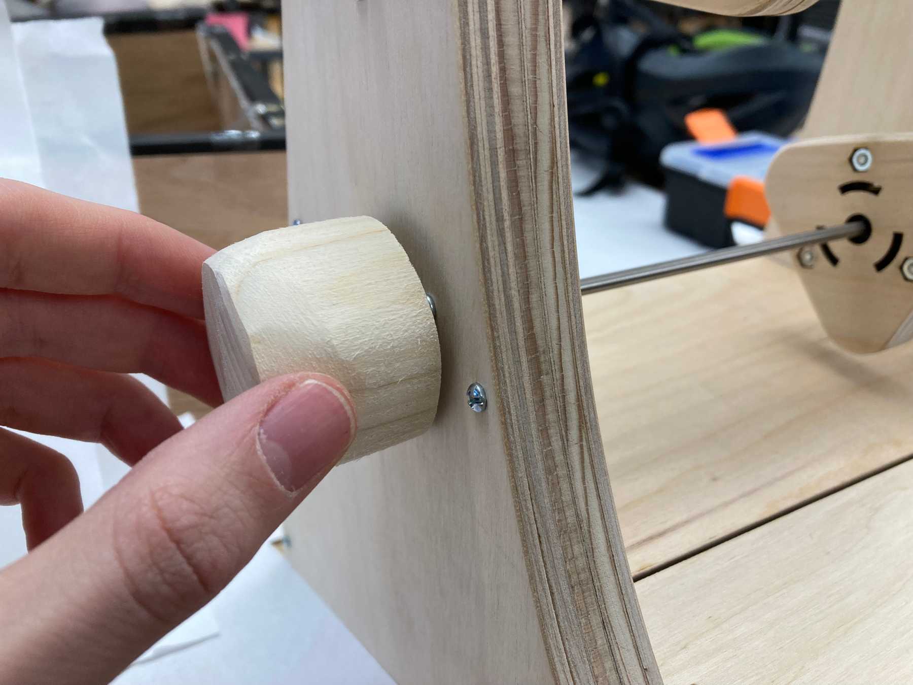
The final step was to build knobs for the four encoders on the left wall. I started by just sanding a piece of wood to get a feel for the size.
I then used a drill bit to cut out cylindrical pieces. These were much cleaner and felt/looked nicer, however I needed a connection piece to hold firmly on to the potentiometer.
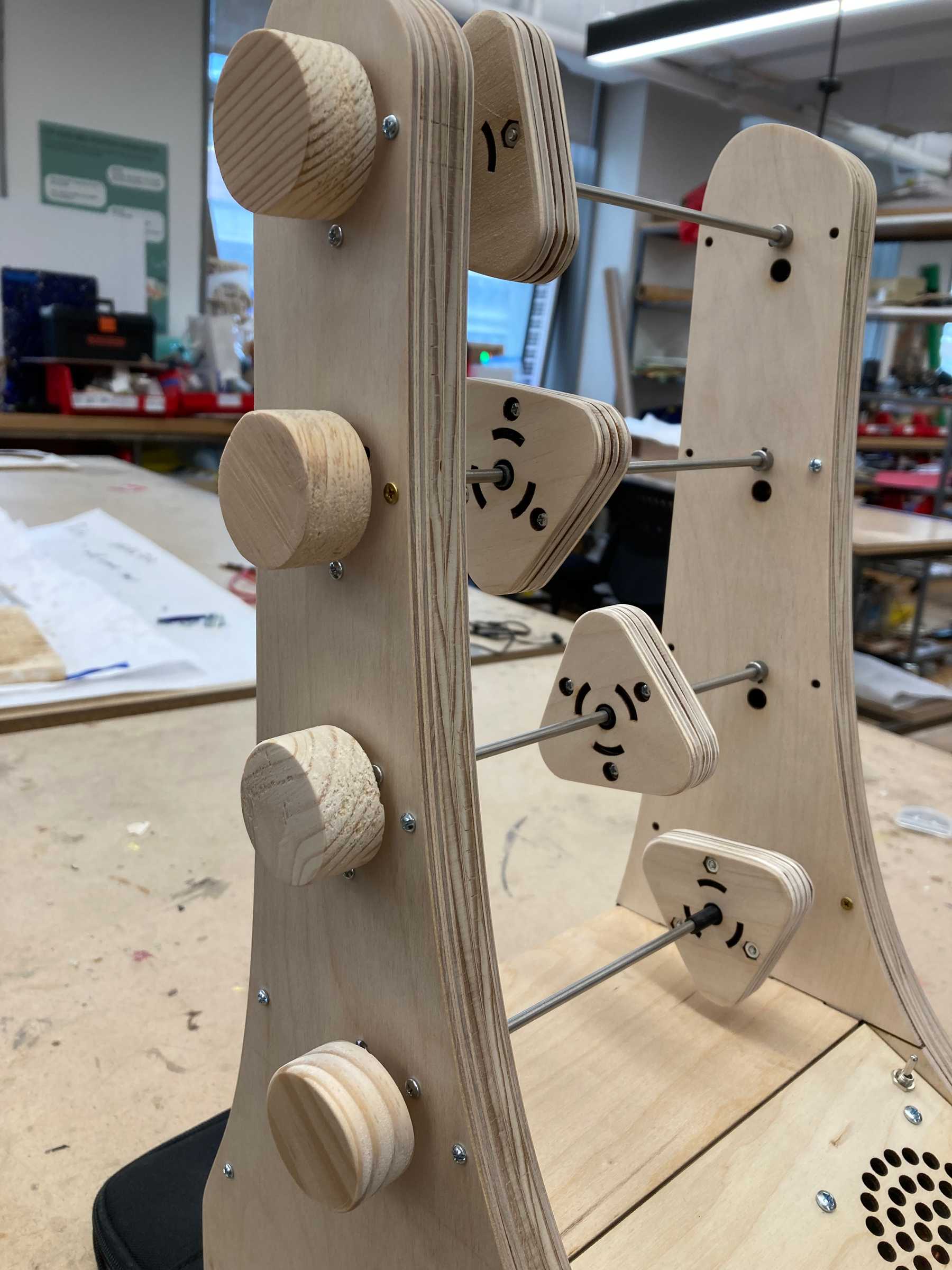 Four knobs cut from various scrap materials
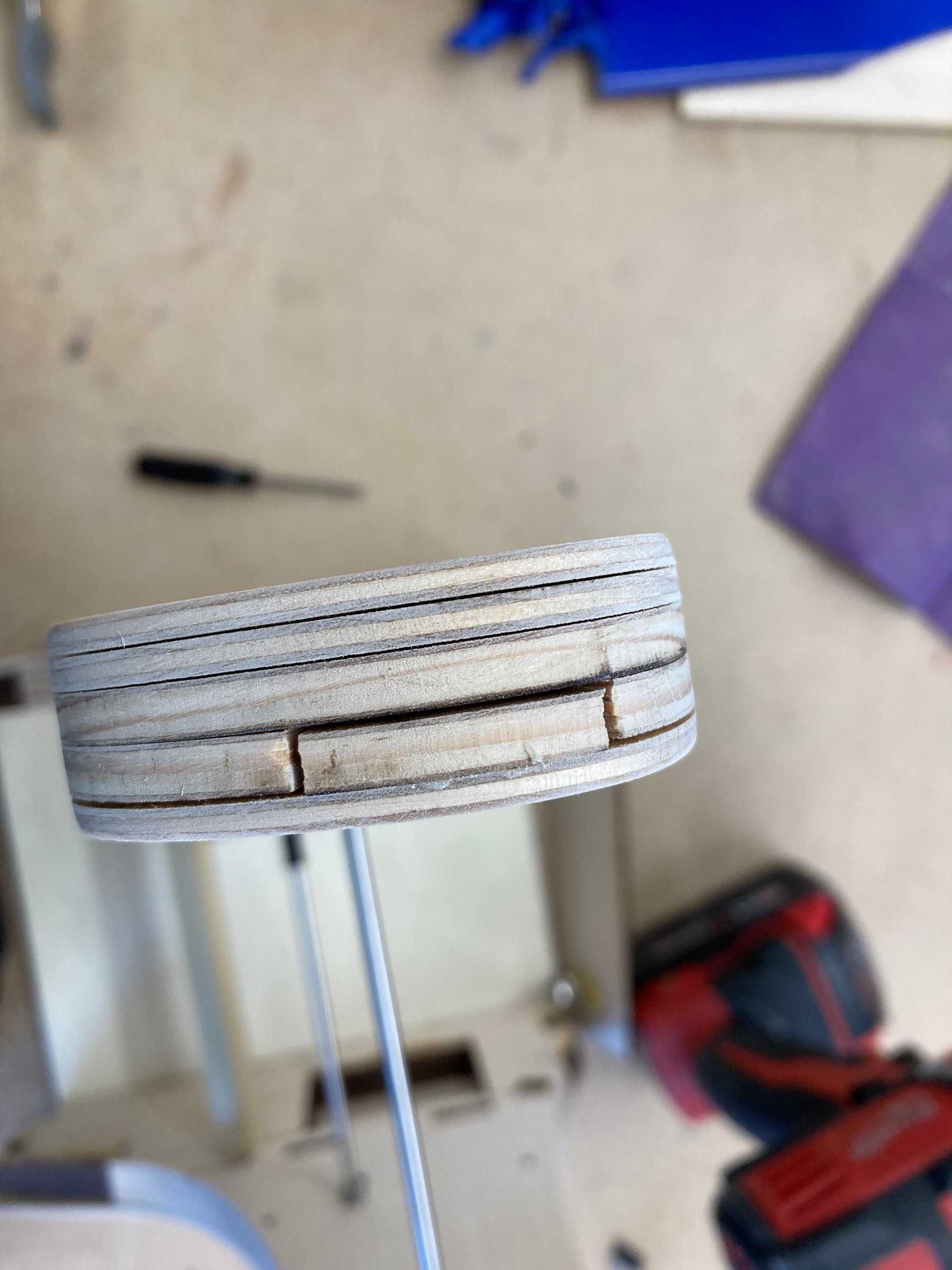
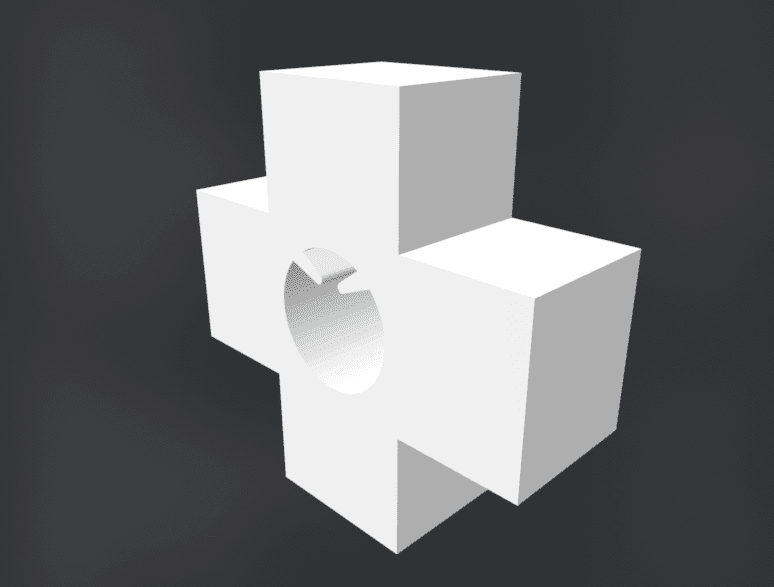
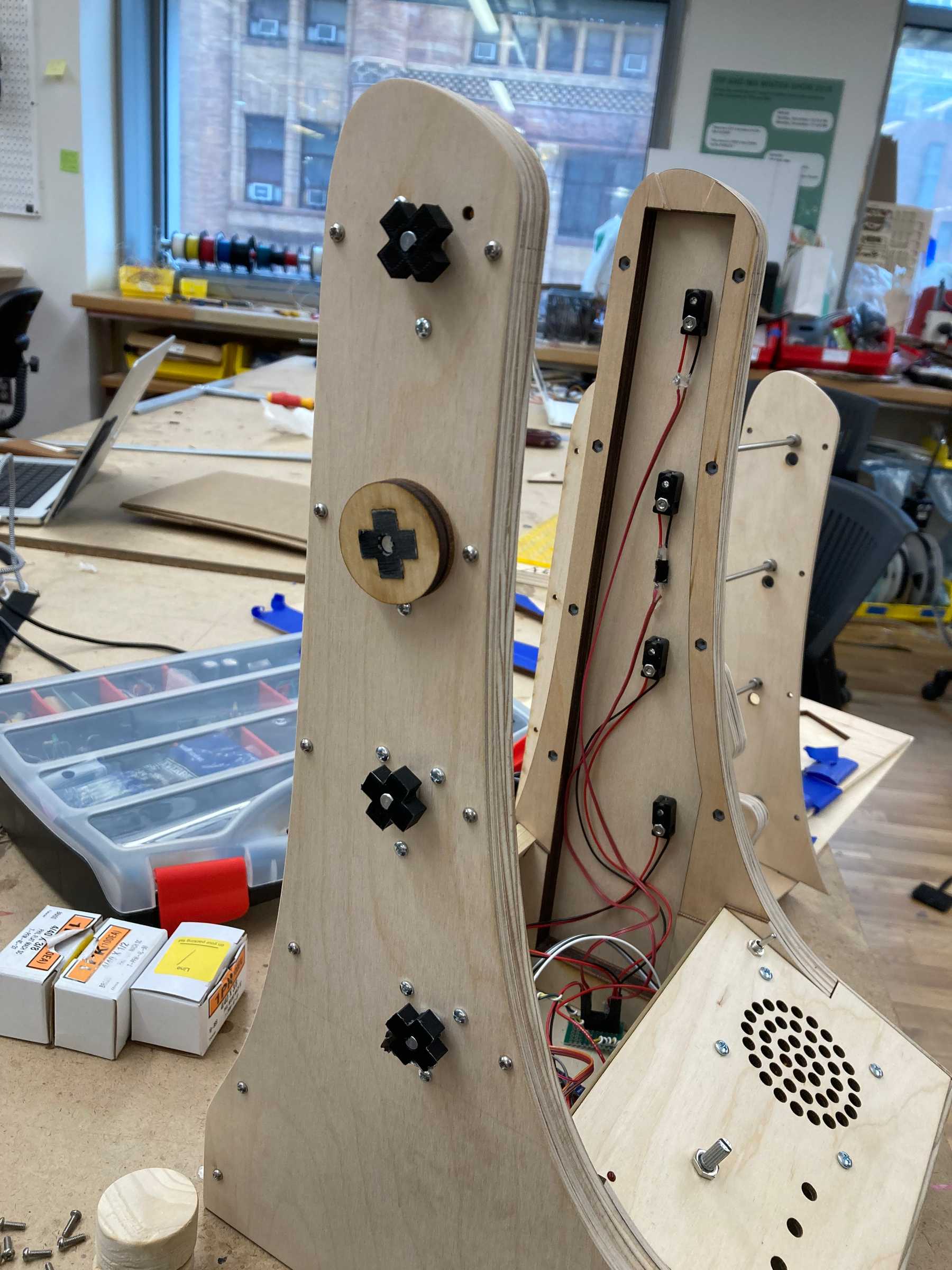
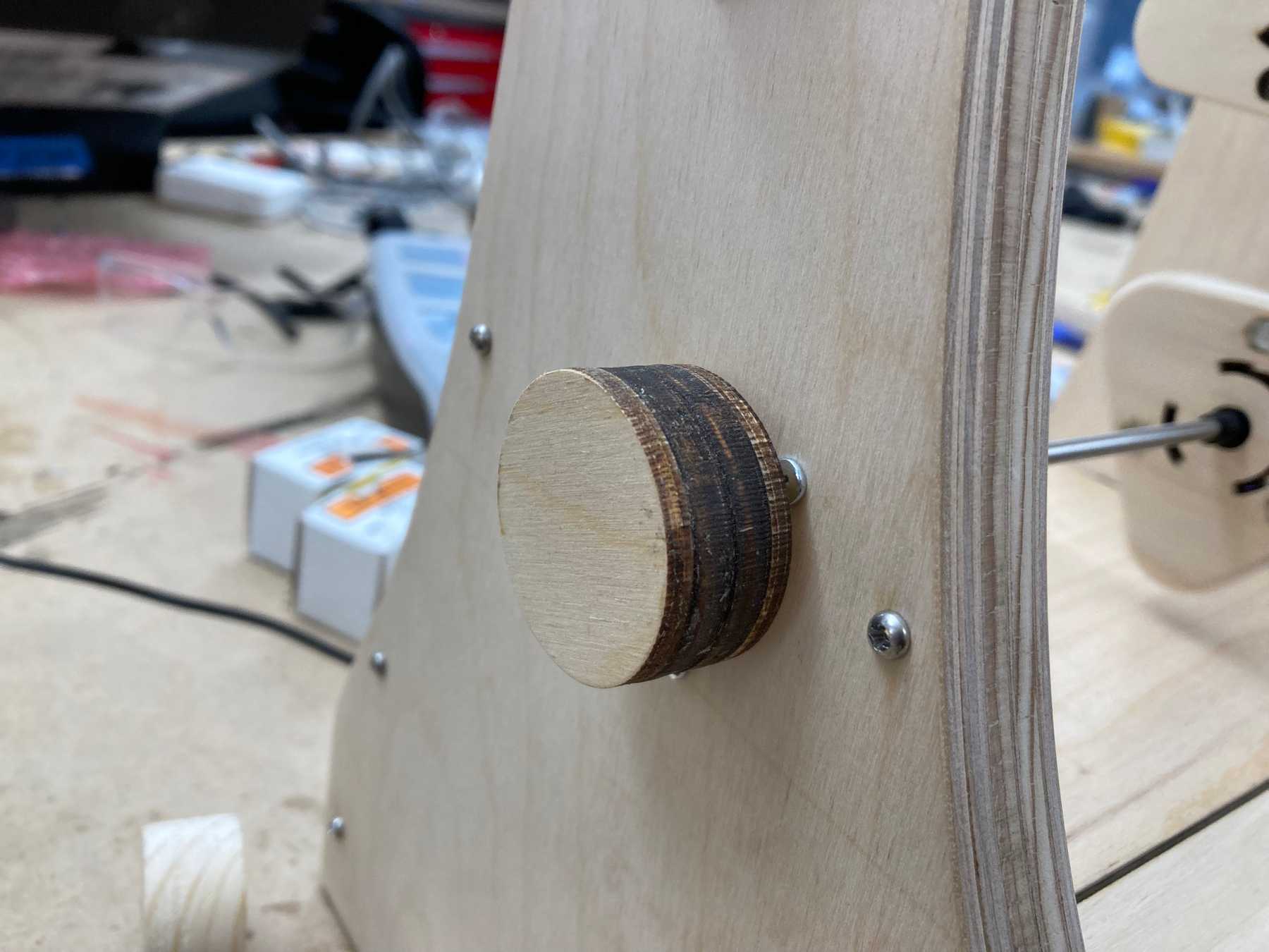
For the final design, I 3d printed an insert and laser cut circular layers of wood.
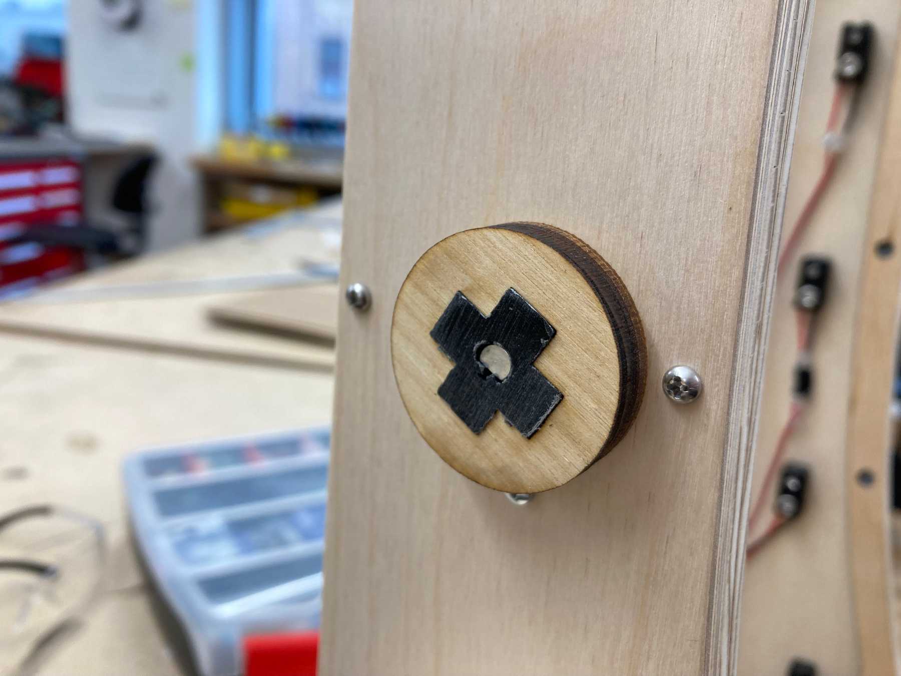 Half of the knob showing the insert
Finishing and Painting
It was now time to take everything apart so that I could finish the wood and paint the knobs and spinners.
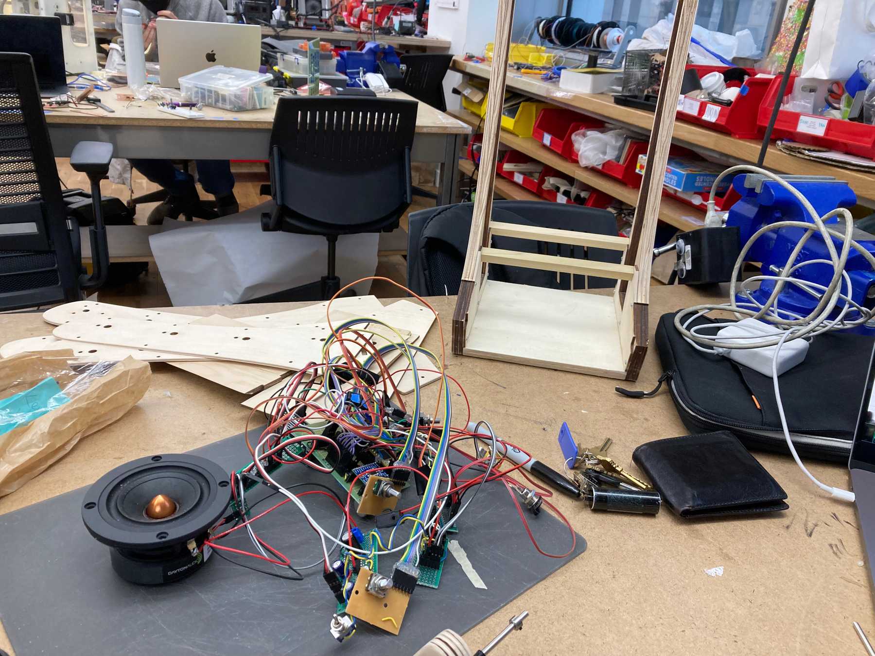 Ever so carefully removing the electronics
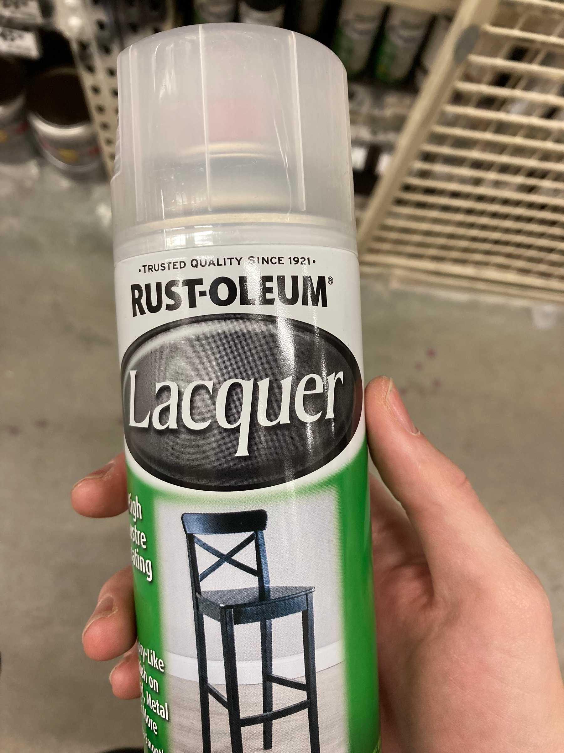
I used a clear spray-on lacquer for the wood, since I wanted to retain its bright natural color.
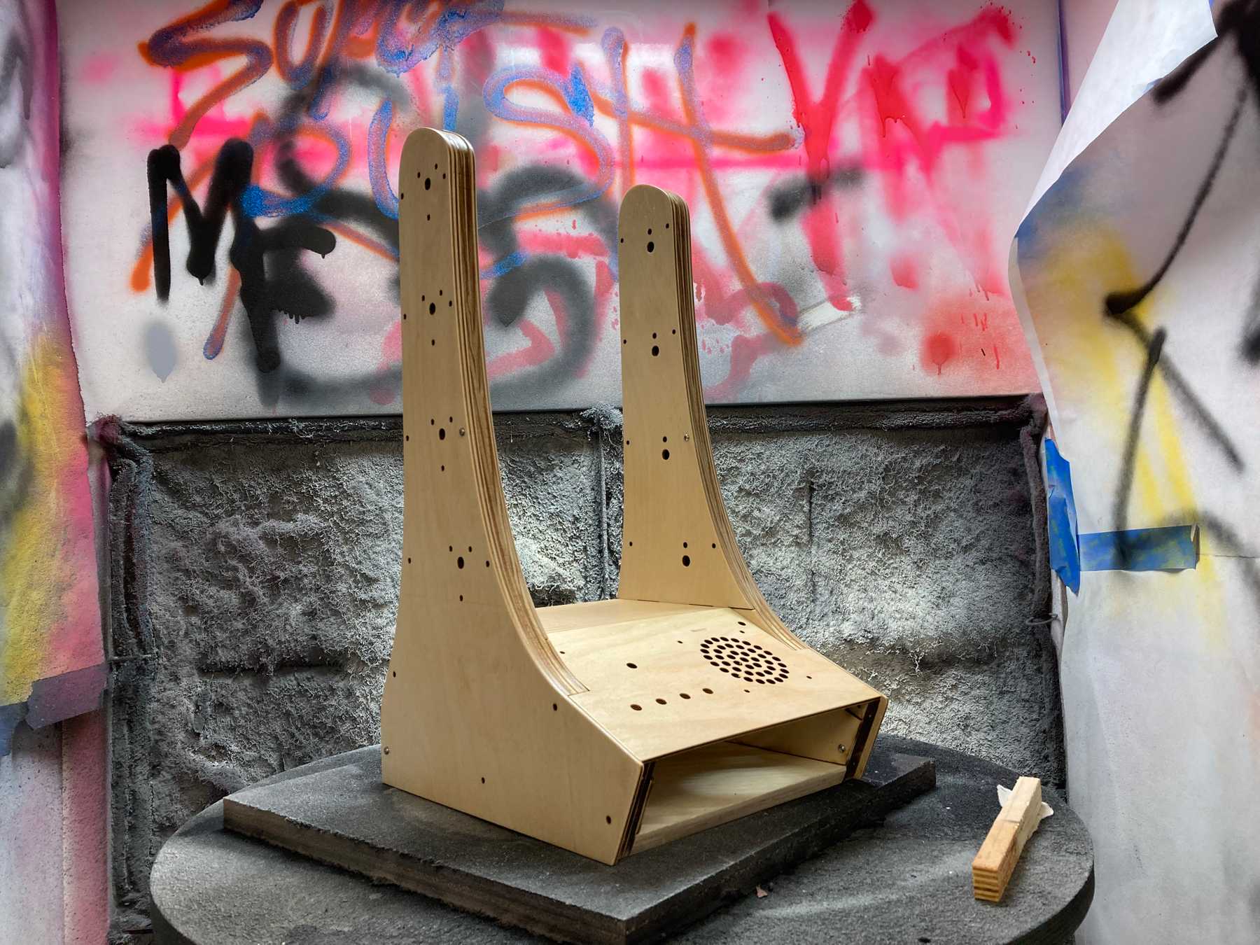
I first sprayed multiple layers on to the disassembled pieces.
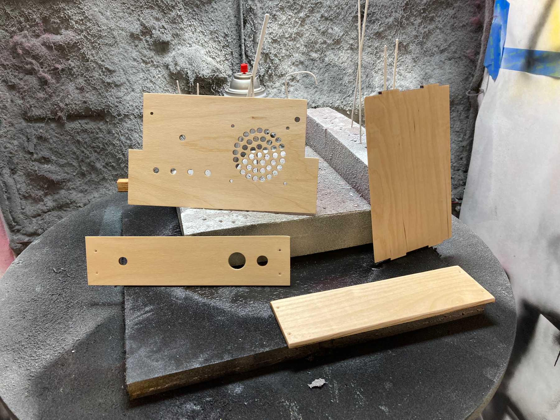 Spraying lacquer onto the panels
I then partially assembled it and added another few coats. I taped off the inner sections that I did not want finished (not pictured).
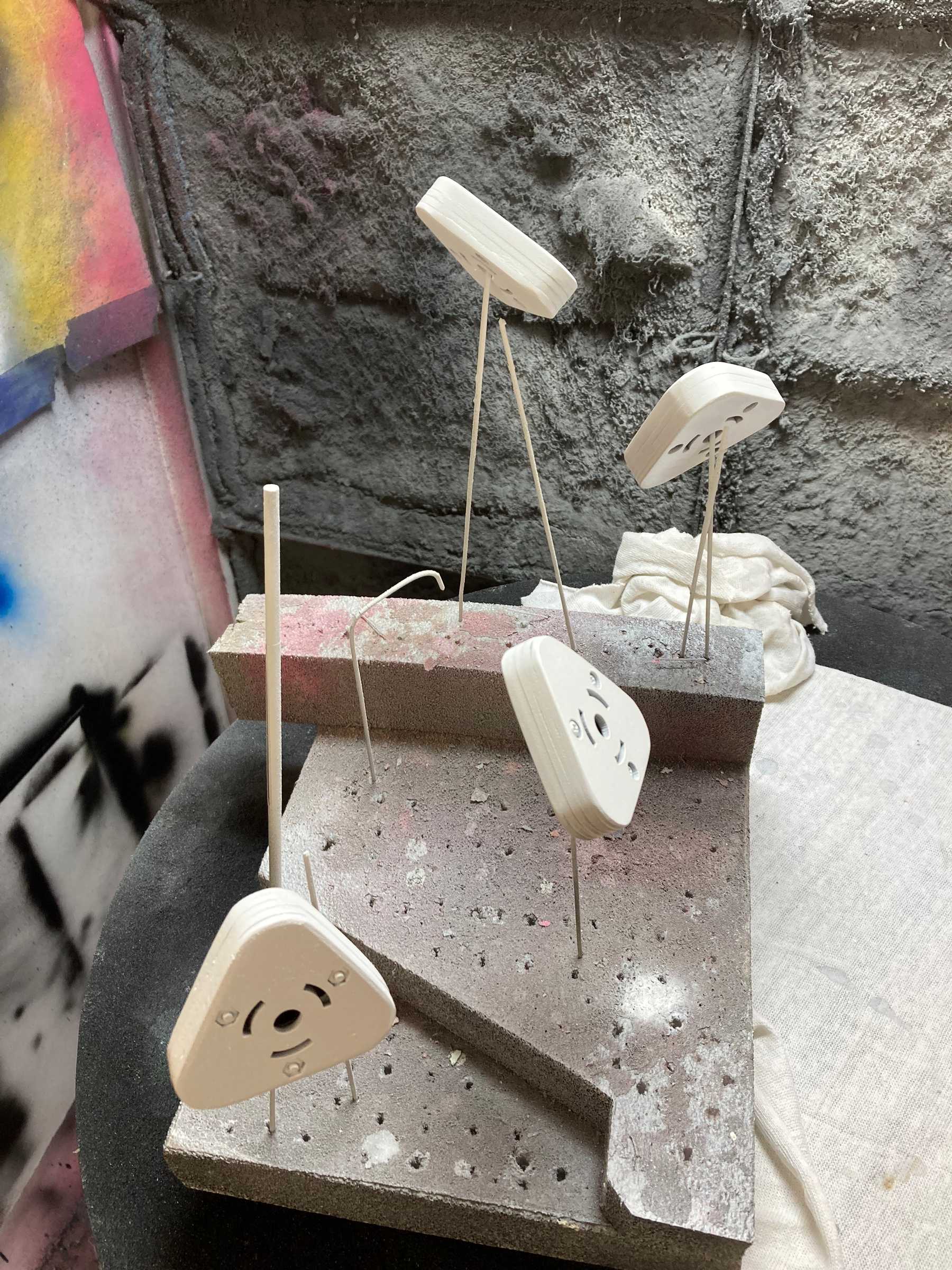
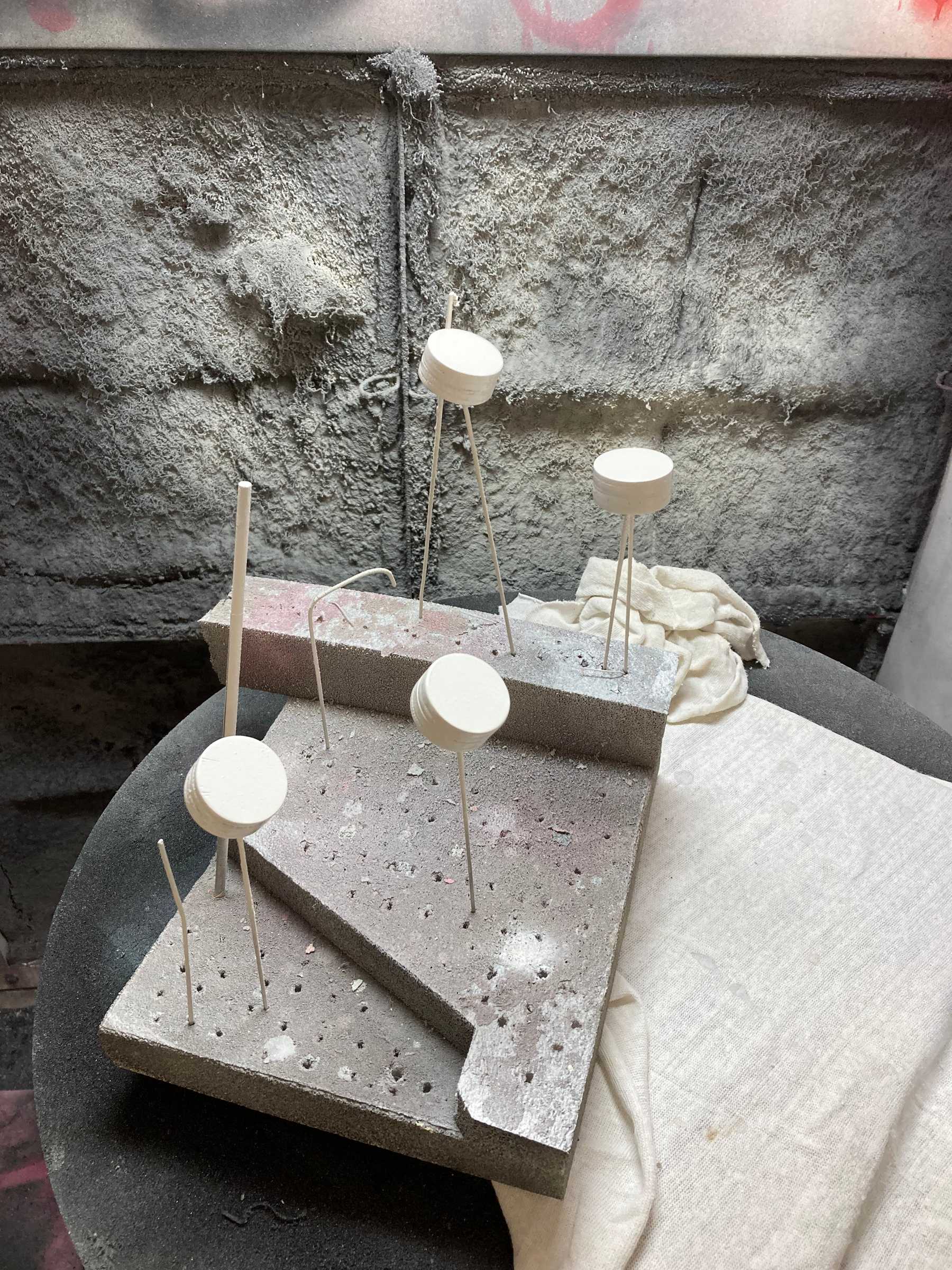
I primed the spinners and knobs in white to prepare them for acrylic paint.
After everything dried, I added the electronics back in and miraculously everything worked.
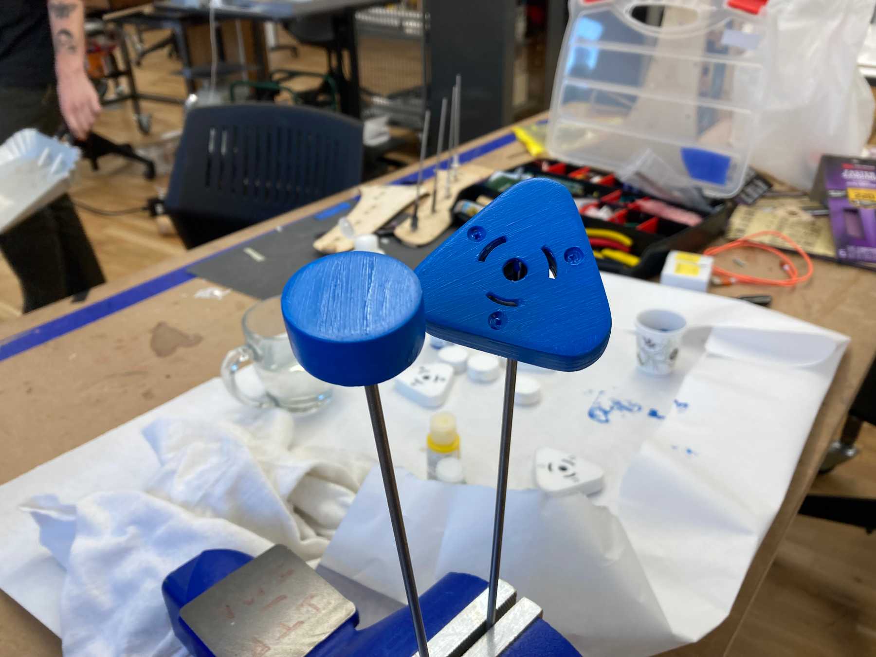
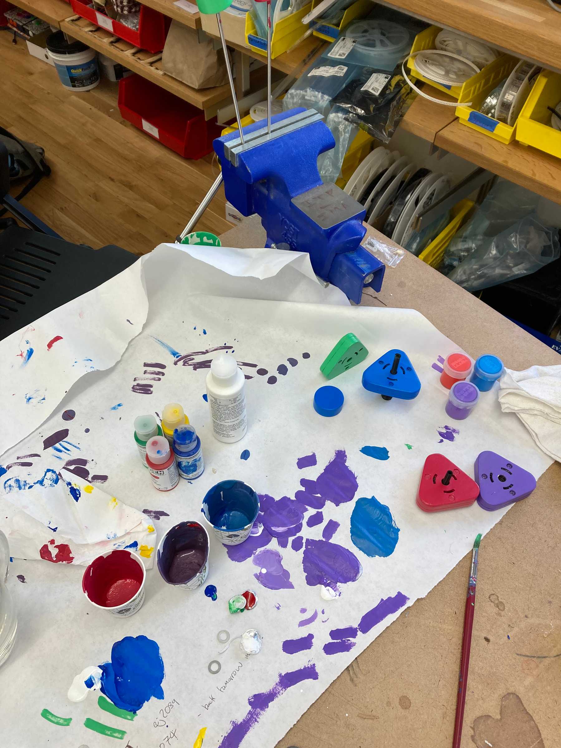
I painted each pair of sliders and knobs a different color. I didn’t really plan out the pallette in advance, but wanted something playful.
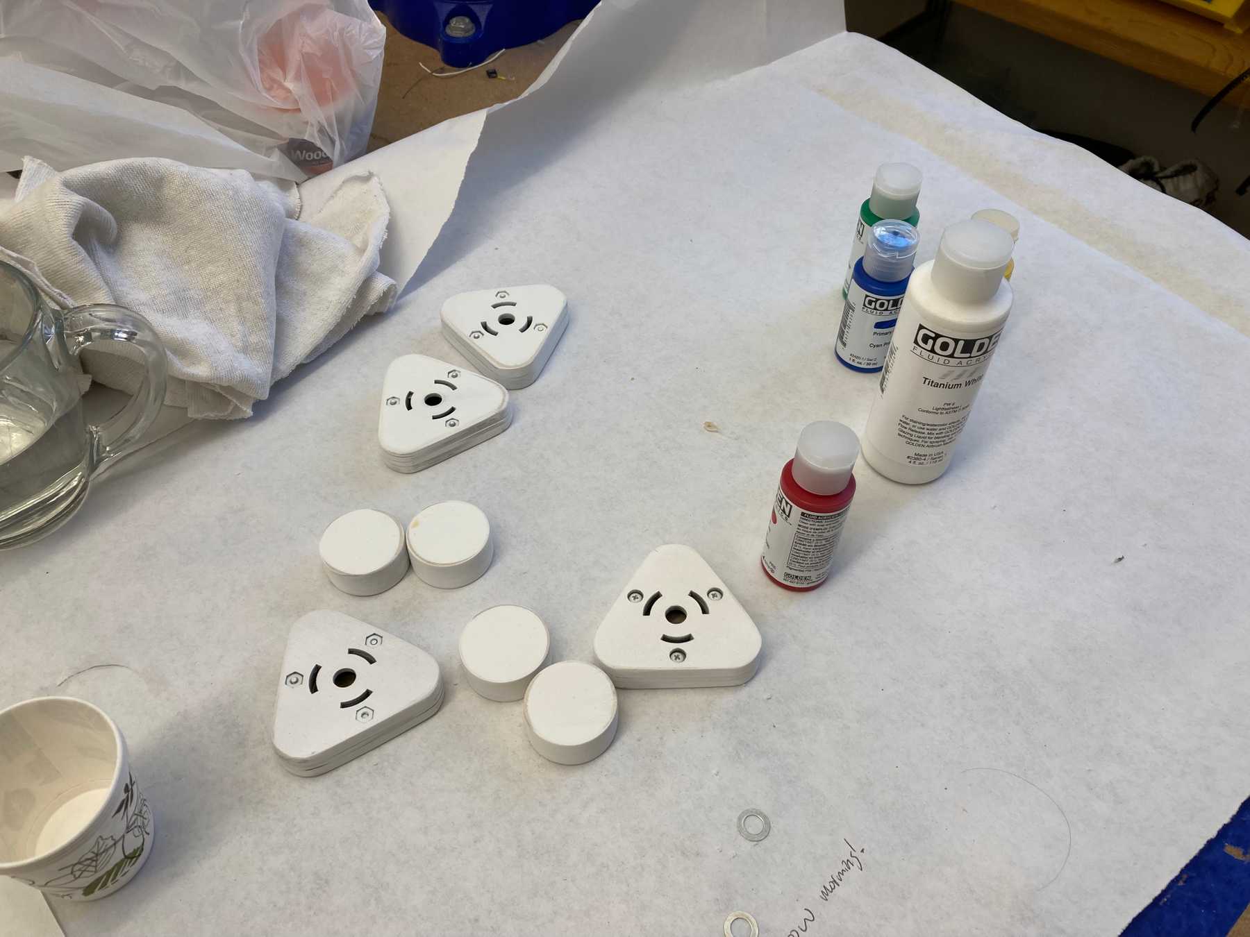 Preparing to paint the knobs and sliders
Final Result
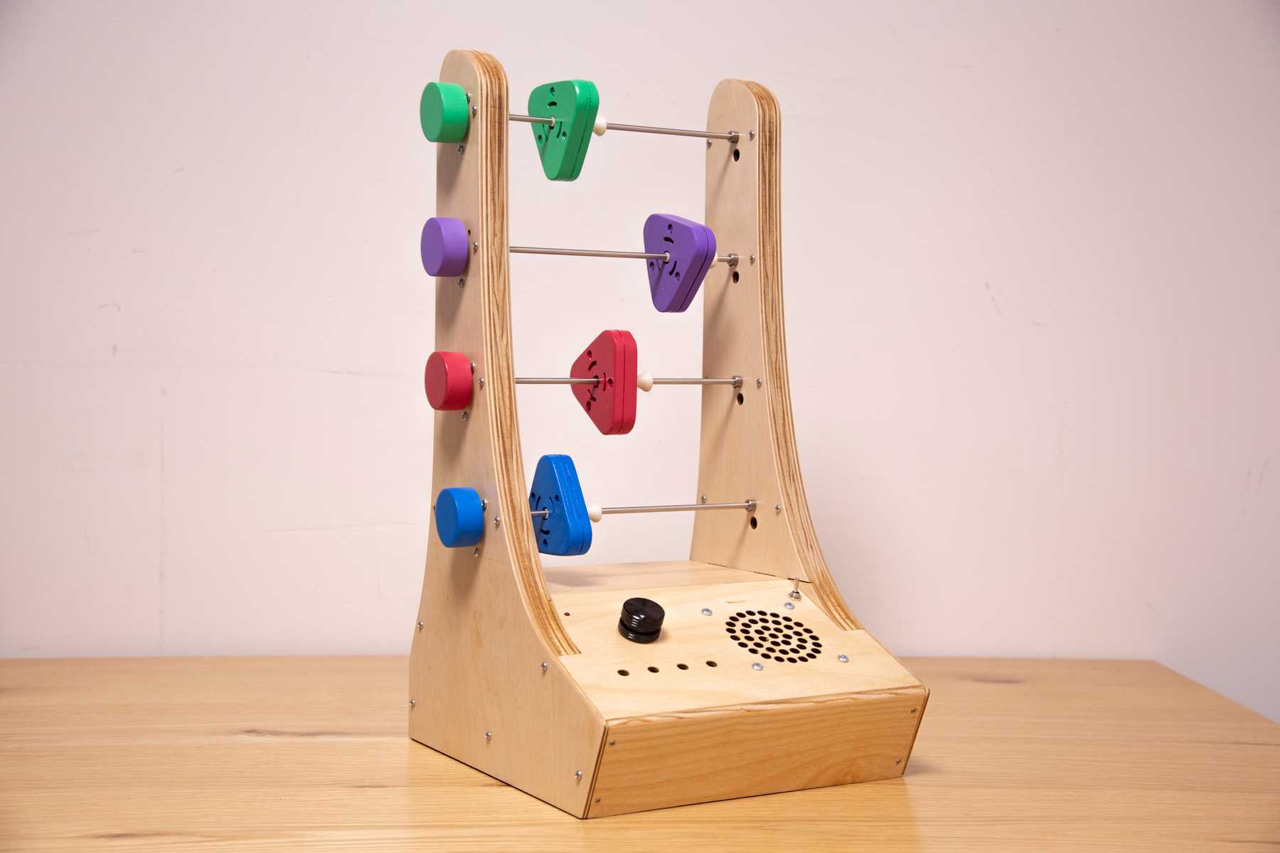
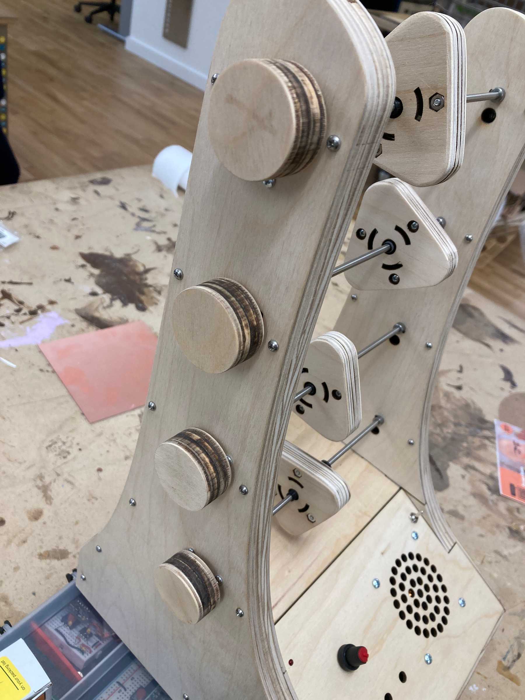
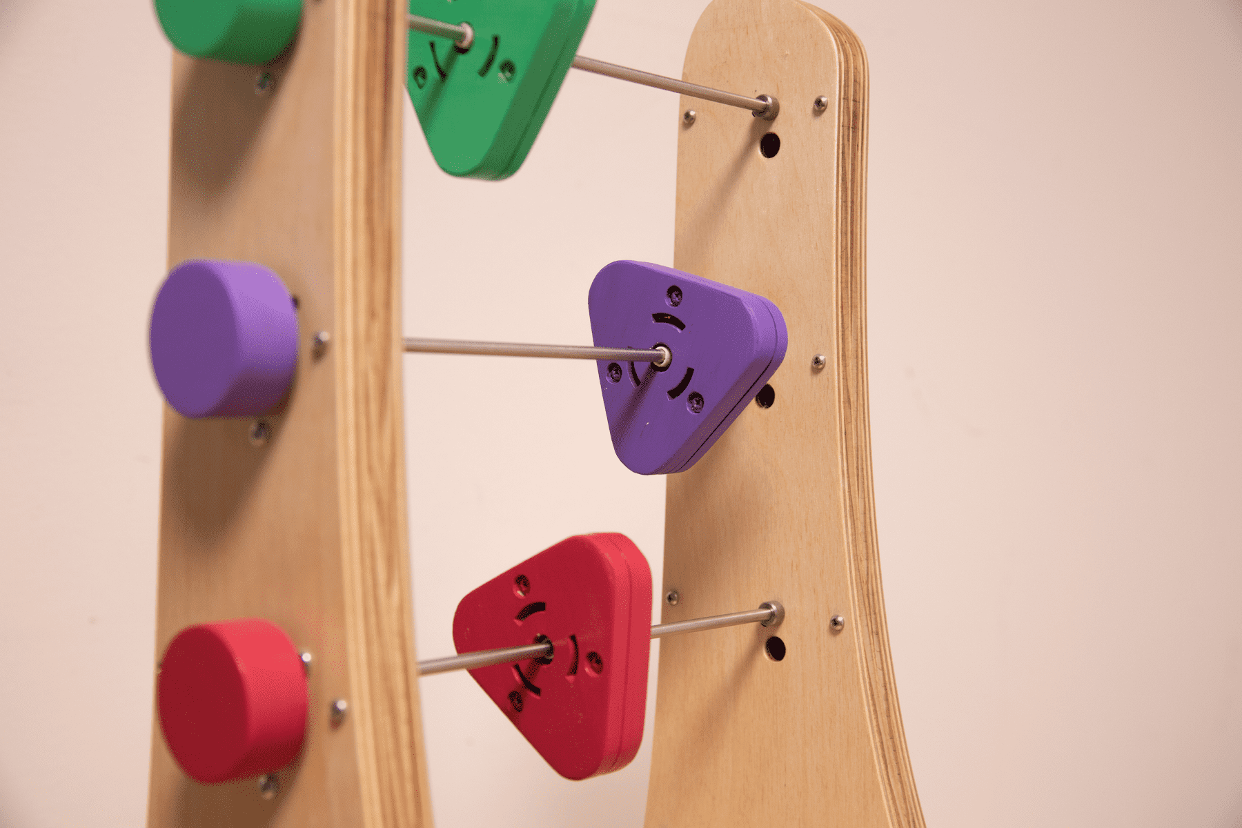
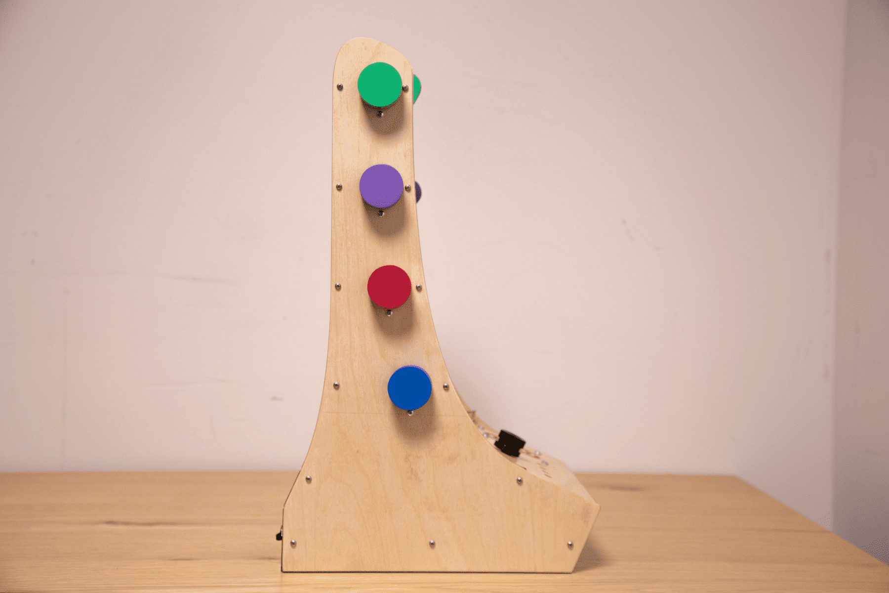
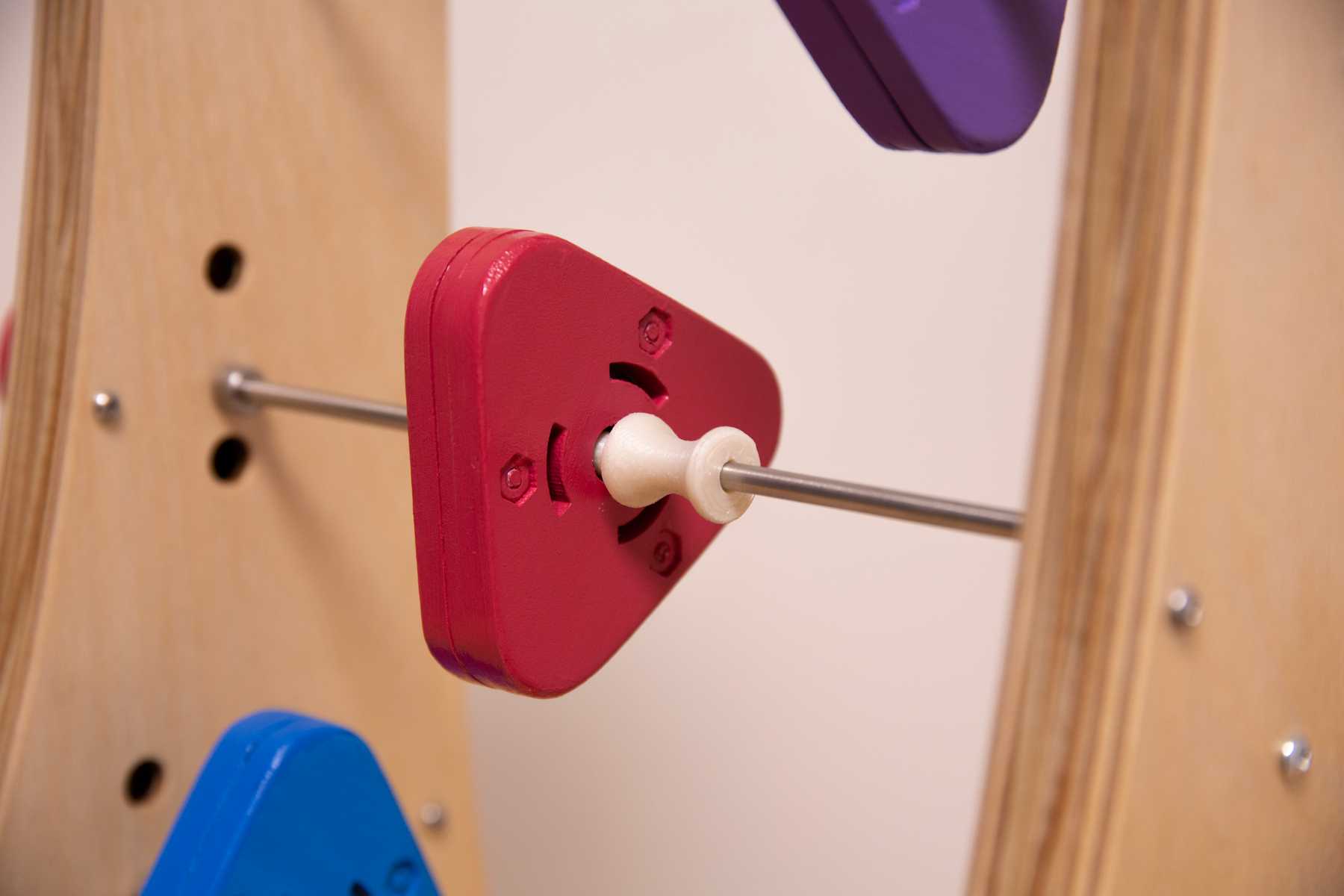
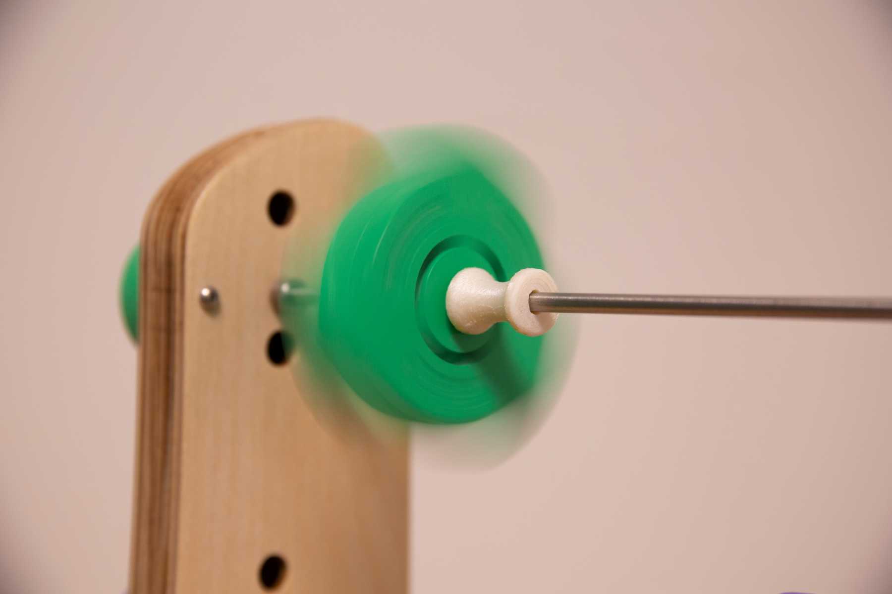
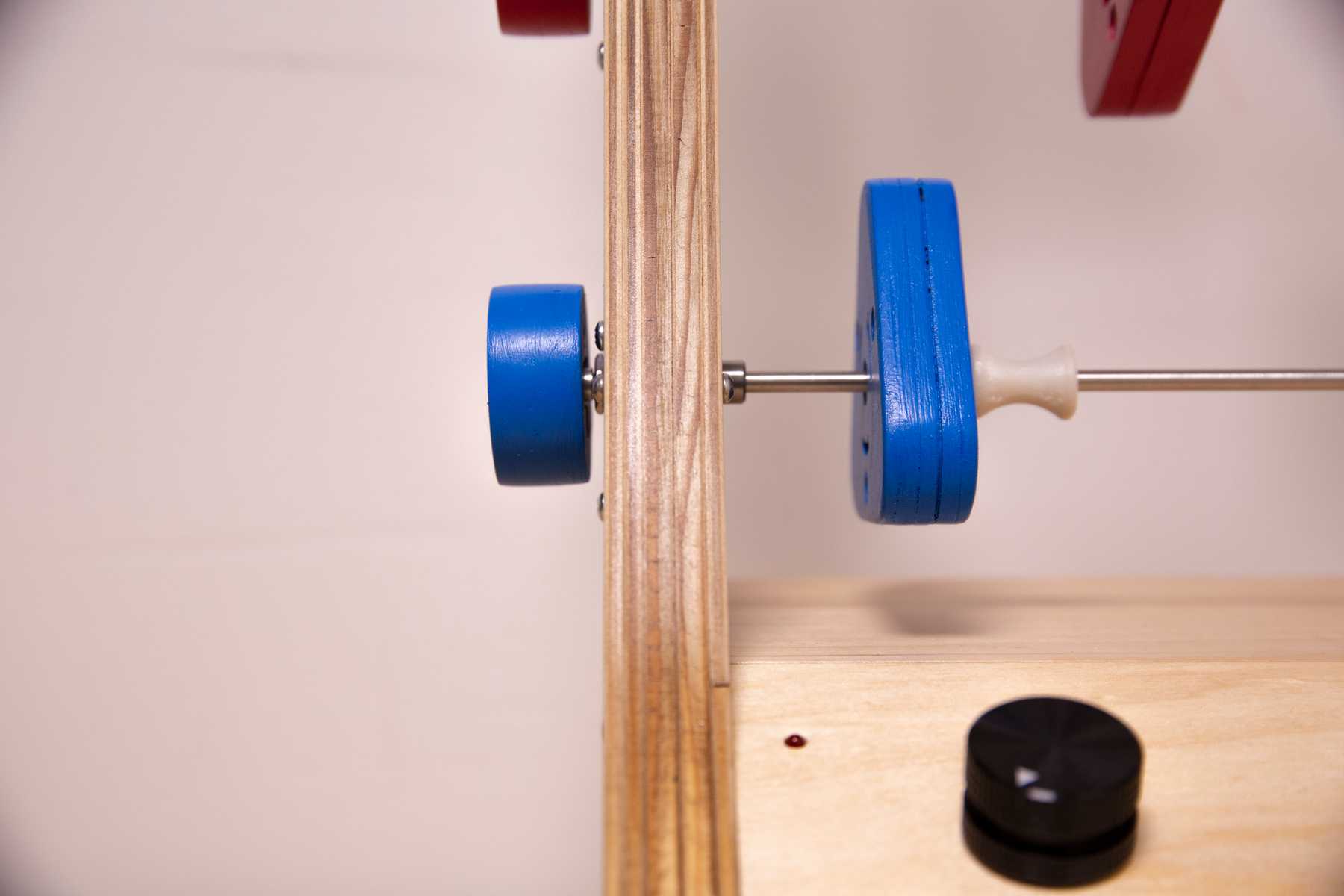
And here are some nicer photos of the final product!
