Pendular
December 07, 2021
NIMEDigital FabricationI am excited to present Pendular, a collaboration with Marcel Wang.
Video coming soon!
Overview
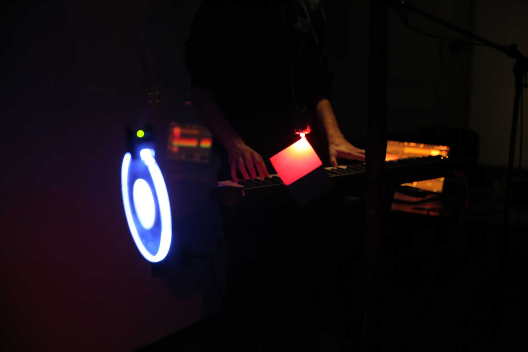
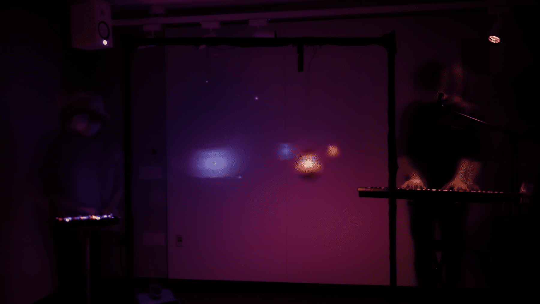
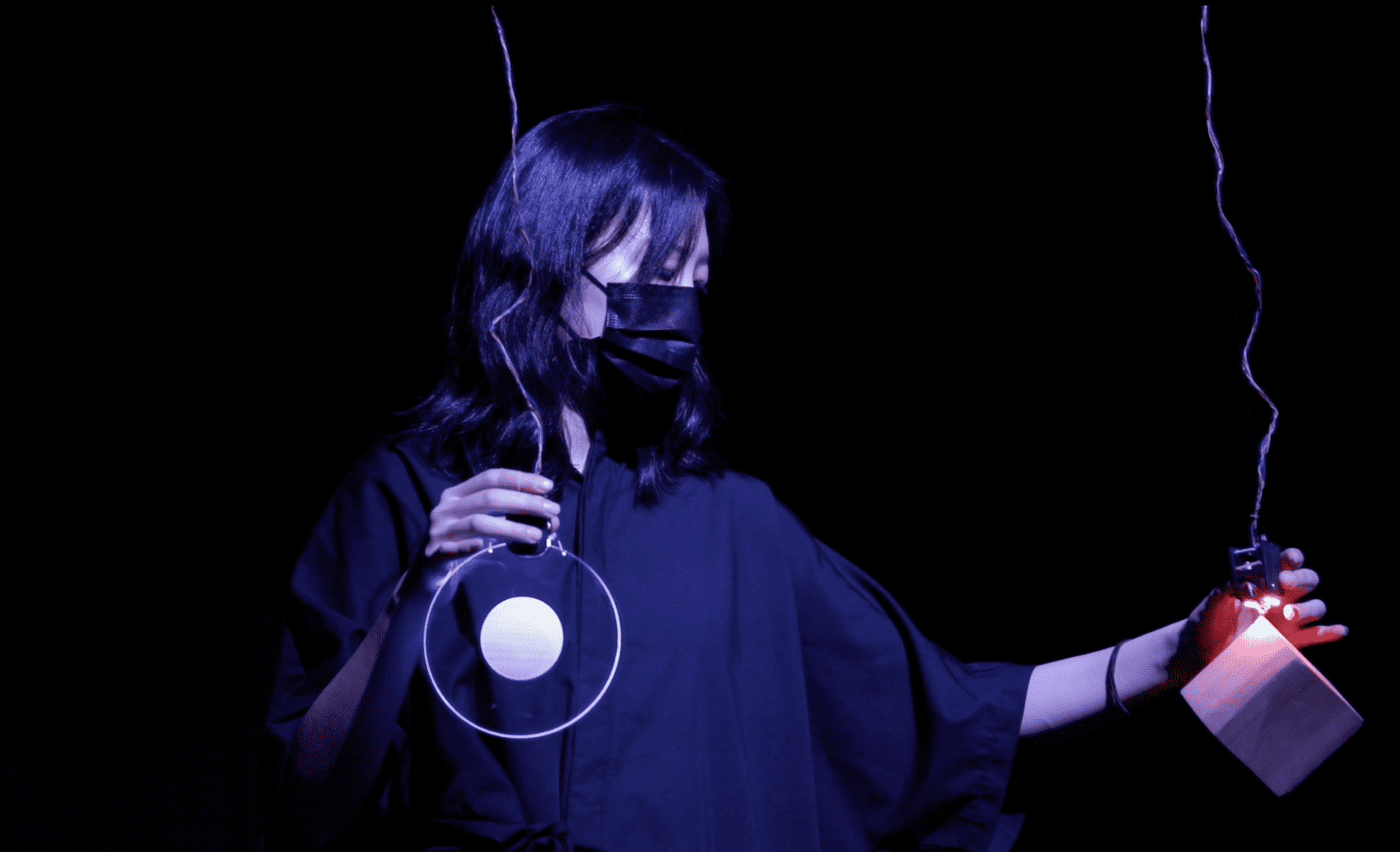
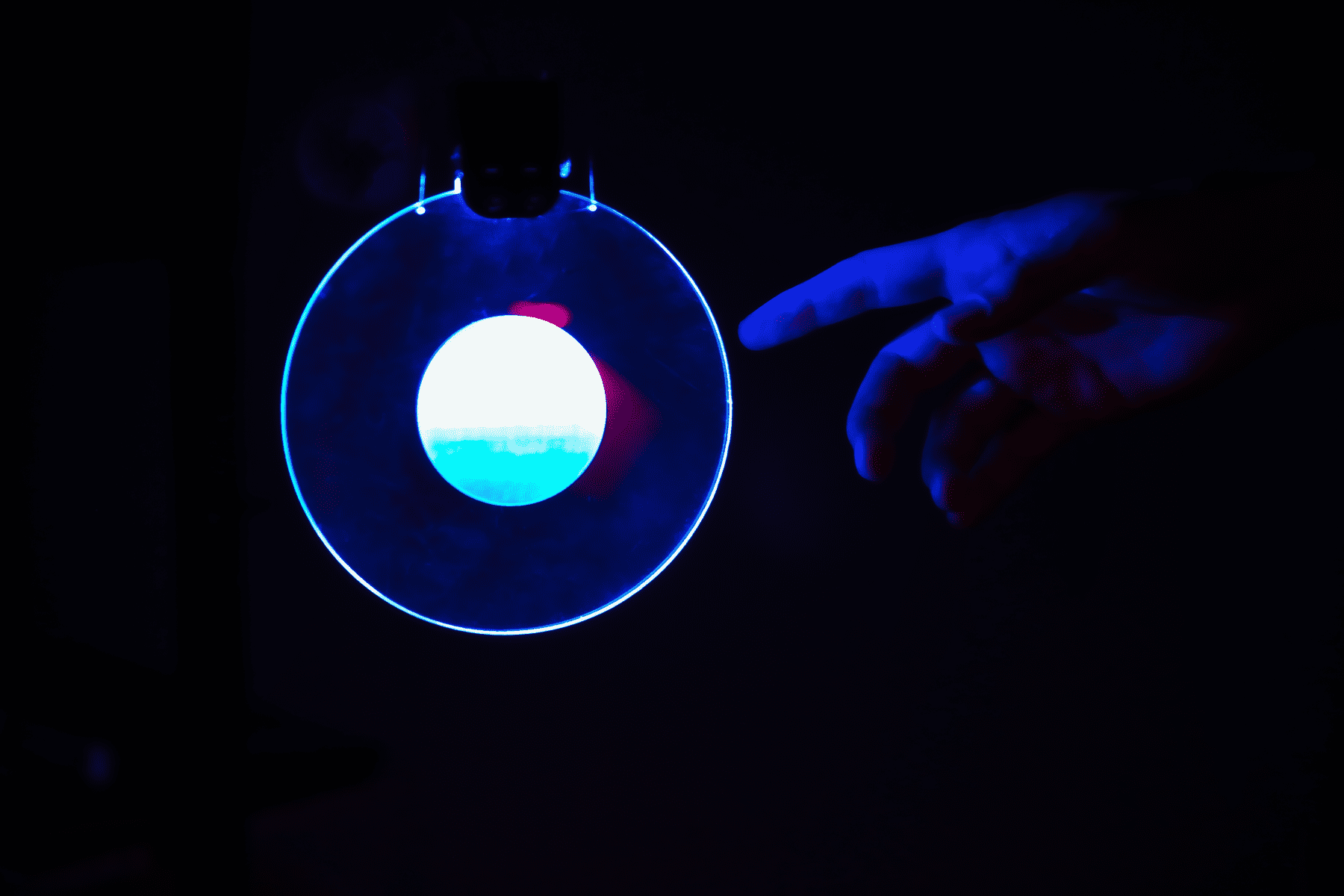
Pendular is an interactive musical system that explores the physical motion of hanging objects as a method for manipulating synthesized music. Using wind and light, we work in tandem to control the environment to which these objects react. As the objects swing and spin through the air, their movements are interpreted as sonic transformations ranging from calm and predictable to chaotic and random.
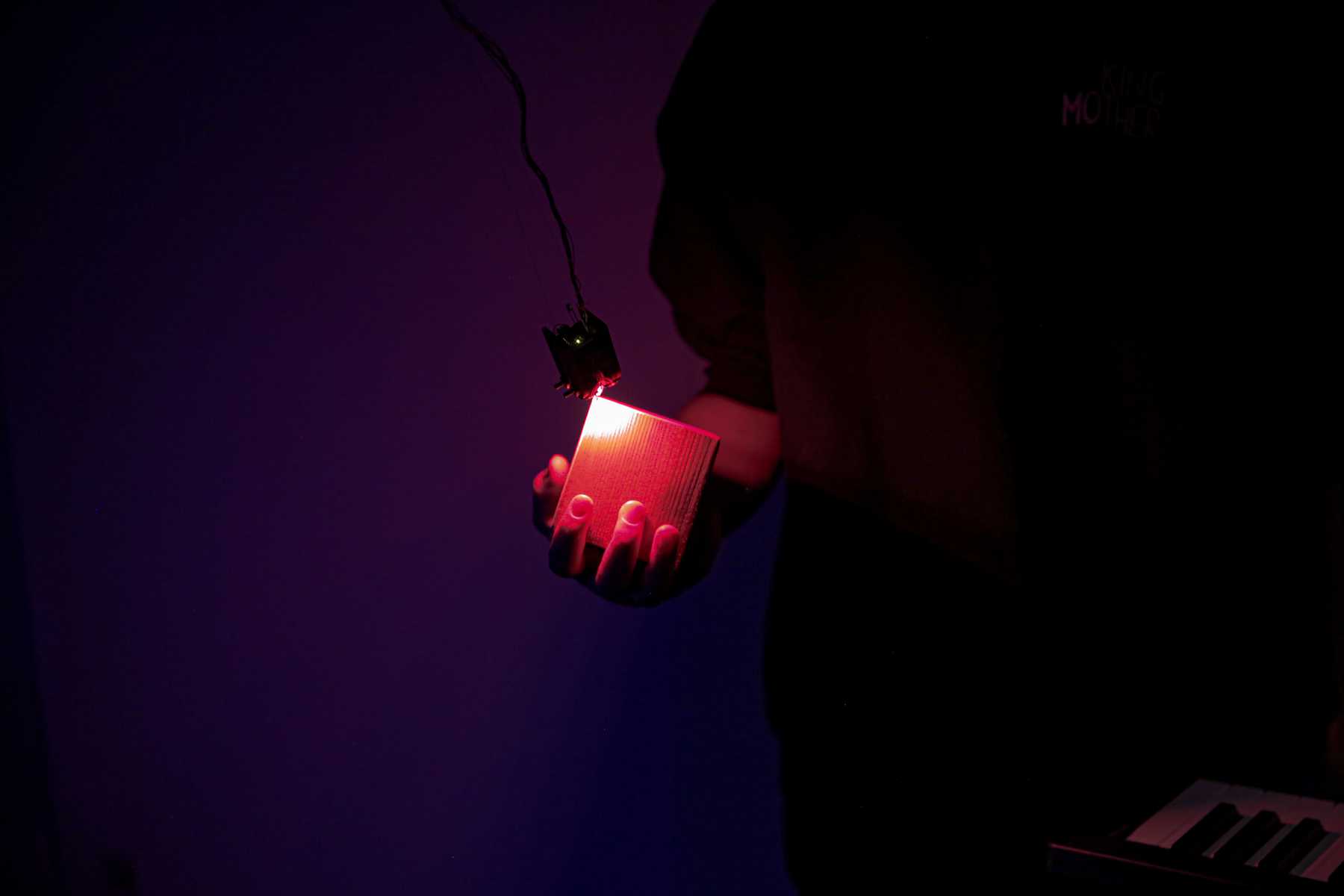
Two objects, a flat circle and a cube, hang side by side. The cube controls a synthesizer and the circle controls effects on live vocals.
 Performance at the ITP NIME show -- Dec 12 2021
Initial Concept
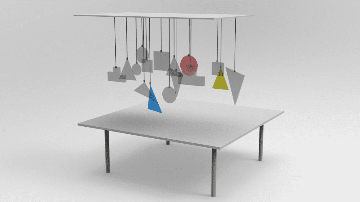
For our initial concept we were inspired by force and pendular motion as the basis for sound creation. We wanted to capture both the calmness and the turbulence of the natural world. How could we capture these motions and turn them into sound?
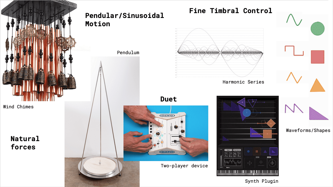 Initial concept and inspirations
We created a concept similar to a wind chime where hanging objects move freely, each suspended by a string.
Each object could sense its own motion with an accelerometer and light with a photosensor, so we could interact with the device using touch, wind, and light sources.
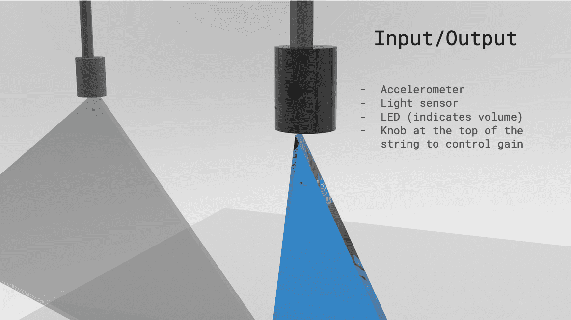 Input and Output of each object
We could perform with the system by having someone control the environment while the other plays the notes that are being manipulated by it.
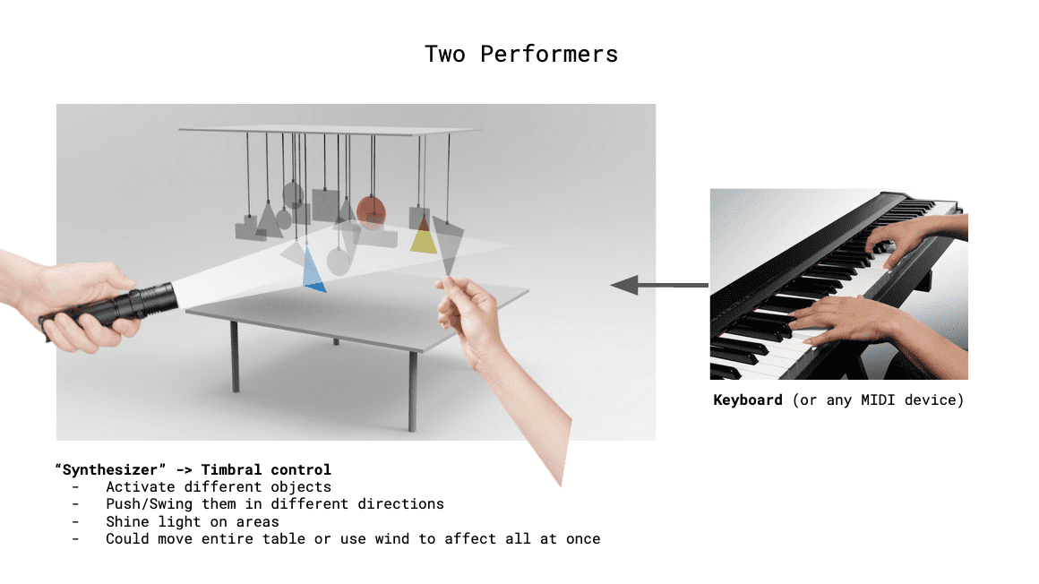 How we imagined the device being played by two people
We imagined a lot of objects all moving subtly together. Ultimately we created just two but this emphasized their motion even more, since they are different sizes and weights.
System Overview
The system consists of two (perhaps more in the future) swinging objects suspended at various heights. Each has an accelerometer, photo-sensor, and LED to illuminate itself. They are connected via a multiplexer to an Arduino which sends data to a custom Max/MSP program that controls parameters in Ableton Live.
Proof of Concept
Just to make sure the idea could work and — most importantly — sounded good we created a proof of concept using an accelerometer attached to a breadboard. We connected and it with a ethernet cable so we could get a sense of the motion.
Proof of concept
Fabrication
The first thing we needed to do was create a way to suspend the objects and attach the sensors.
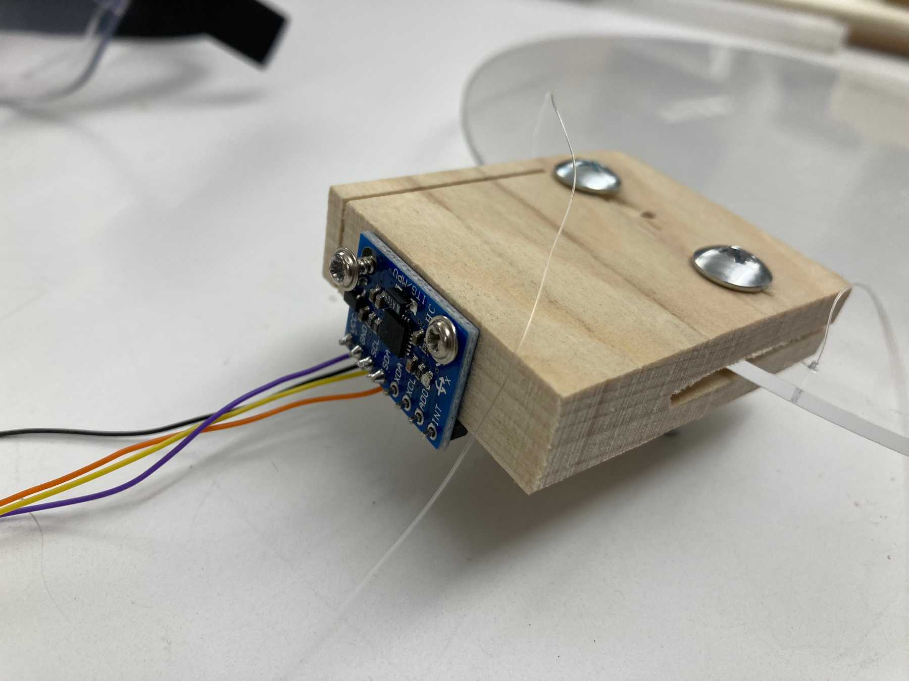
Handmade prototype
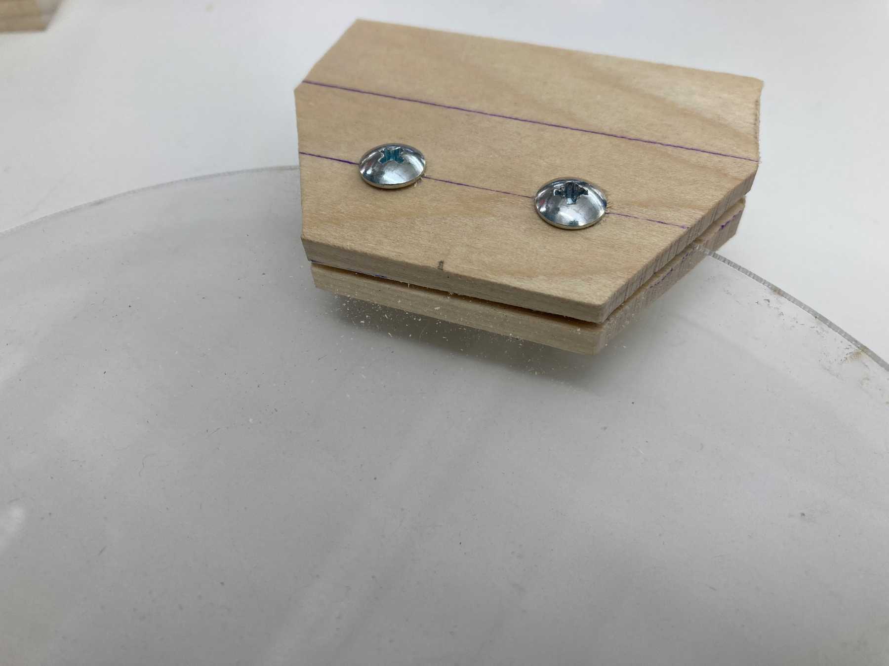
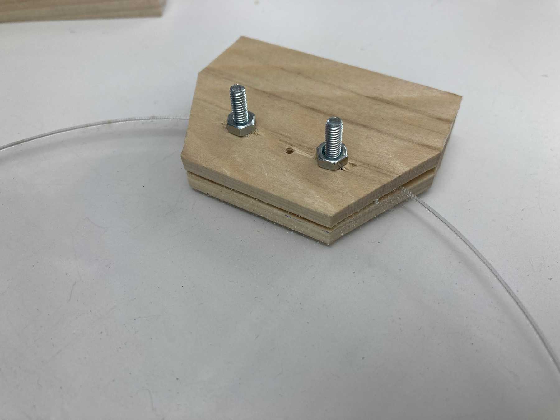
Using the bandsaw and drill we prototyped a wooden piece that we could bolt on to a piece of acrylic that we used as the object. Two holes to attach to the enclosure and two tiny holes to suspend the piece with fishing wire. It was pretty rough but the overall idea seemed to work.
For our first test we drilled the accelerometer directly to the wood. We also cut down the sides because they were in the way of the fishing wire.
Laser cut prototype
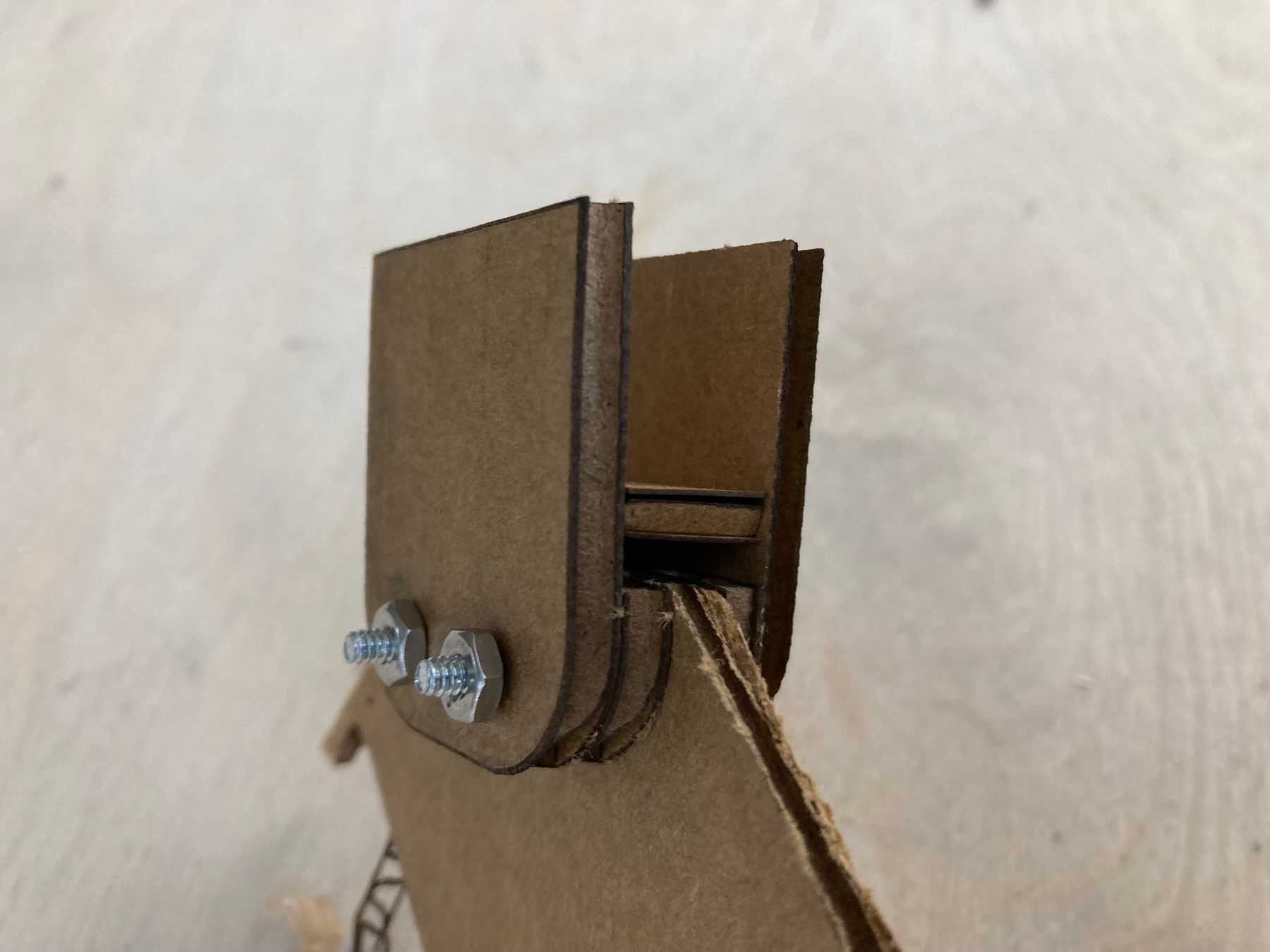
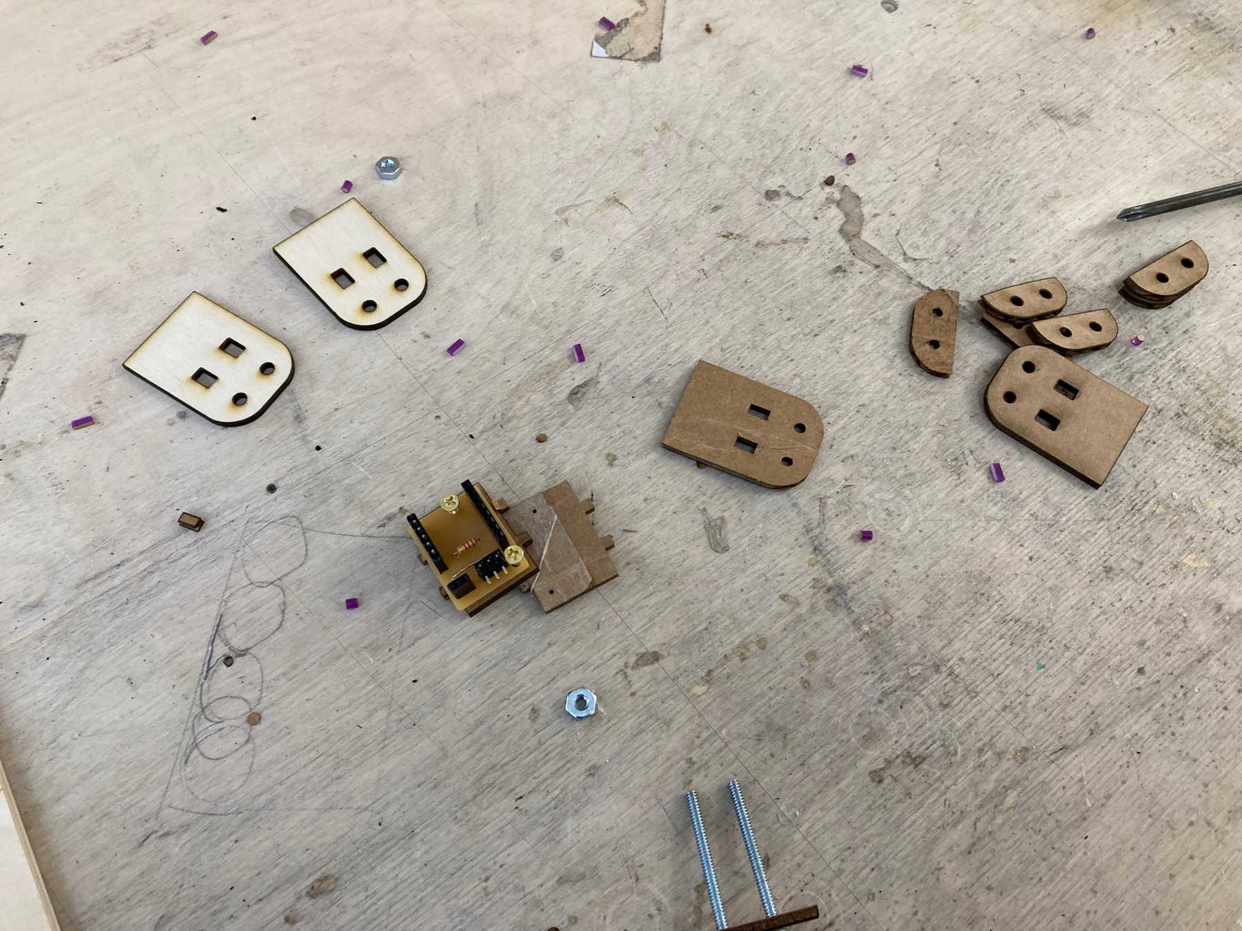
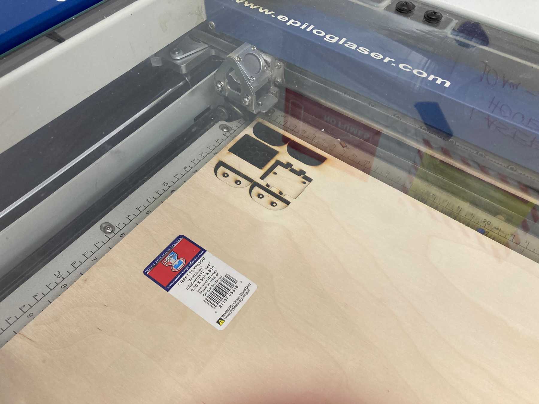
For our next iteration we designed the enclosure in Vectorworks and laser cut the pieces. Starting with cardboard…
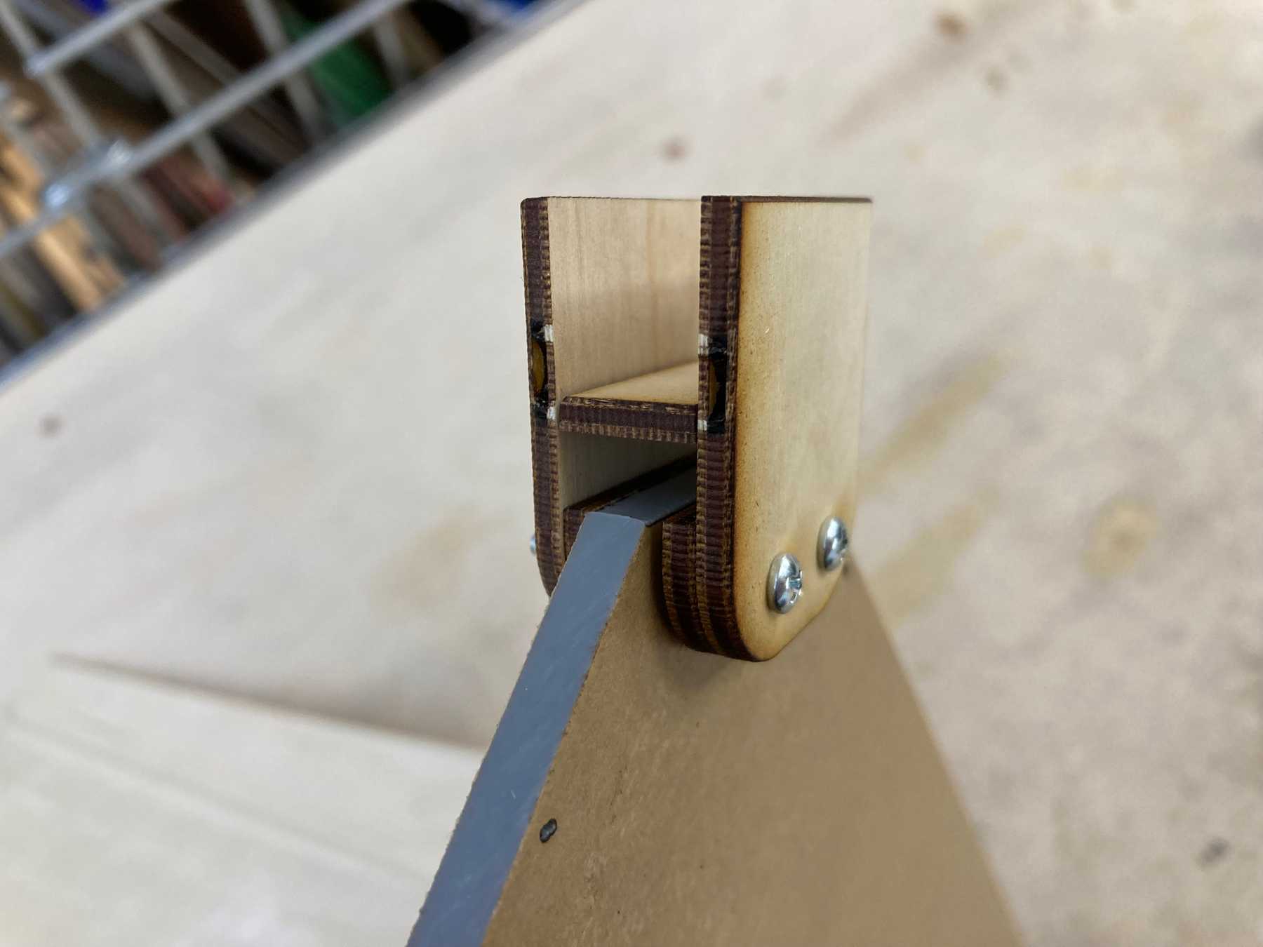
And moving on to wood…
This version of the enclosure assumed that the accelerometer would be placed vertically instead of flat. We soon realized that this posed some problems with the sensor as the most accurate readings come from the flat position.
As a proof of concept it worked well. It allowed us to notice some issues with the design. First, the flat part that the sensor would sit on needed to be thicker so that we could screw into it. It also was not fixed in its position — it would be better for it to have notches in the side so we could sandwich the sensor in without having to glue anything. There also needed to be more space to allow the sensor to be flat.
Version 2
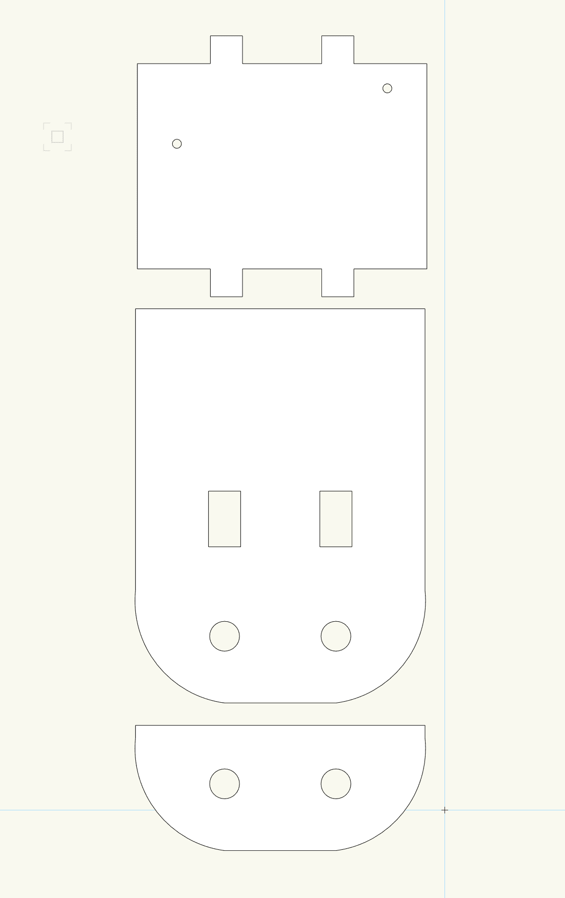
Back to the drawing board! We designed our final enclosure around our newly finished PCB design (more on that below). This version features thicker wood for the sensor base as well as mounting holes and notches so that the whole thing can be put together and taken apart easily.
Starting with cardboard again, we printed the new design.
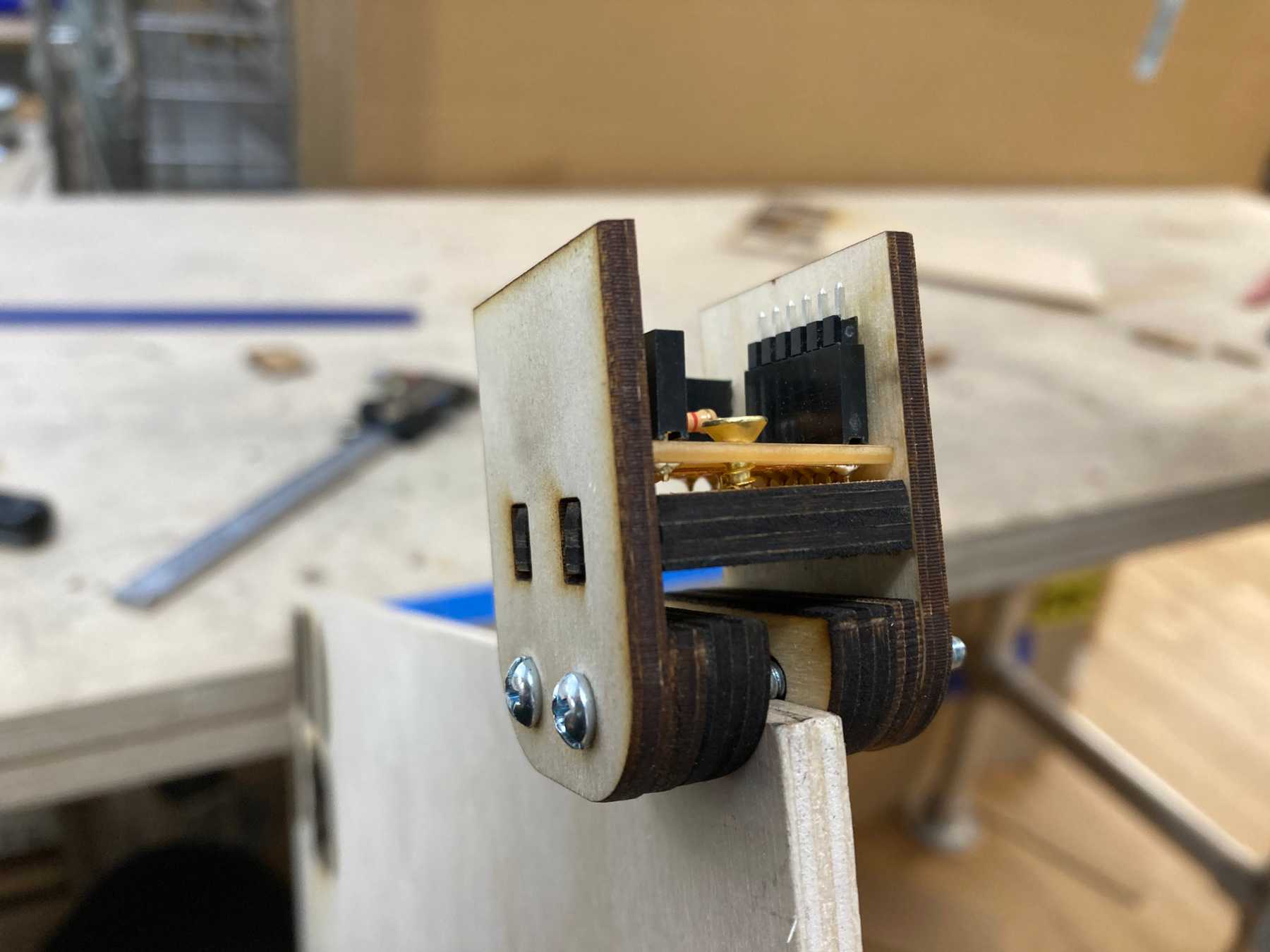
The PCB fit pretty well. The only issue is that there was a bit of space between the bottom of the PCB and the wood. We solved this by adding some washers in between the two surfaces.
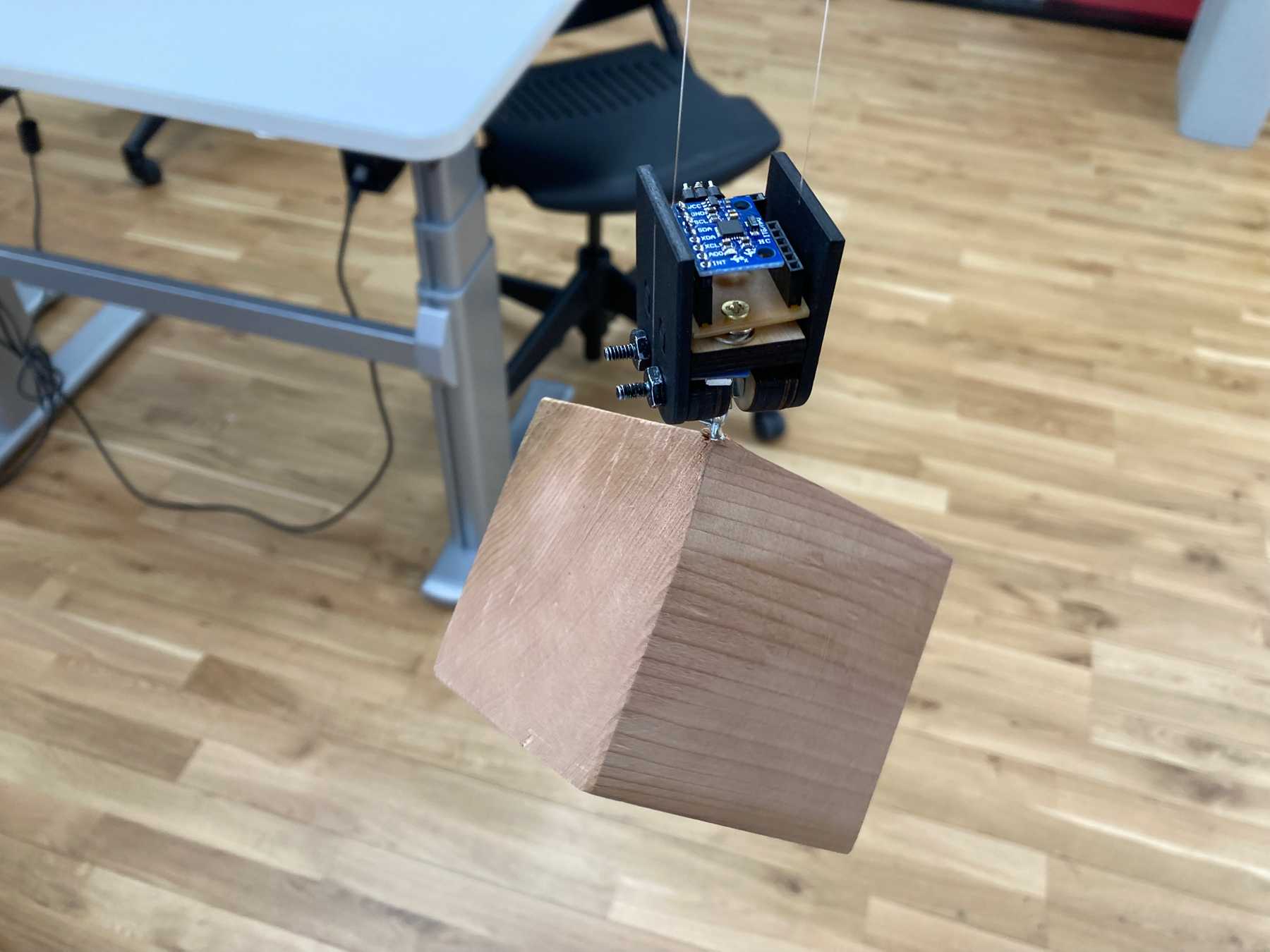
The final enclosure! The PCB fits snugly in between the walls and the bolts hold everything together.
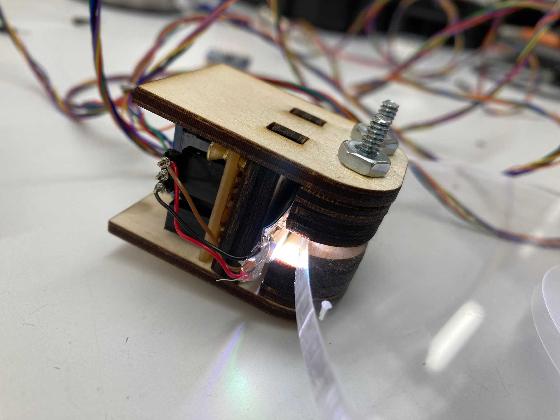 Testing out the LED pointed down on the object
We could now wire everything together. The LED strip fits below the PCP mount and points directly downward to illuminate the acrylic.
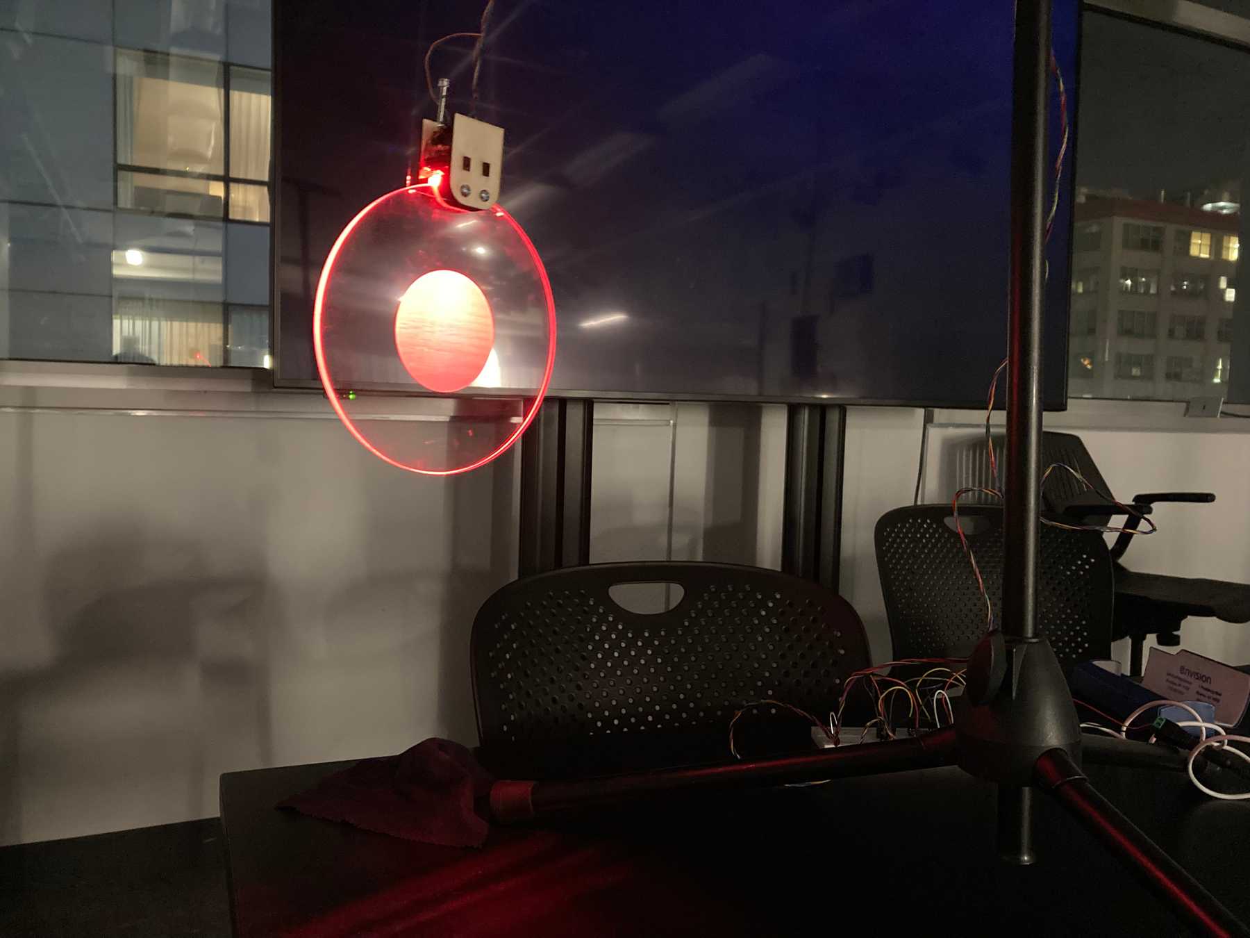 Testing the effect in a darker environment
It works! We tested in a darker environment.
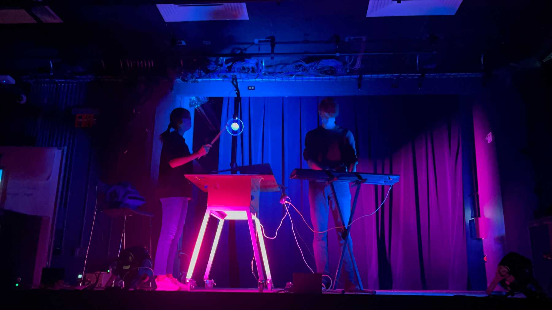 Our first rehearsal using the circle object
With our first prototype working, began building a second. Using the same design, we hooked a wooden cube to the sensor mount. We thought the different weights would be an interesting contrast. The cube is also more natural to hold and manipulate directly.
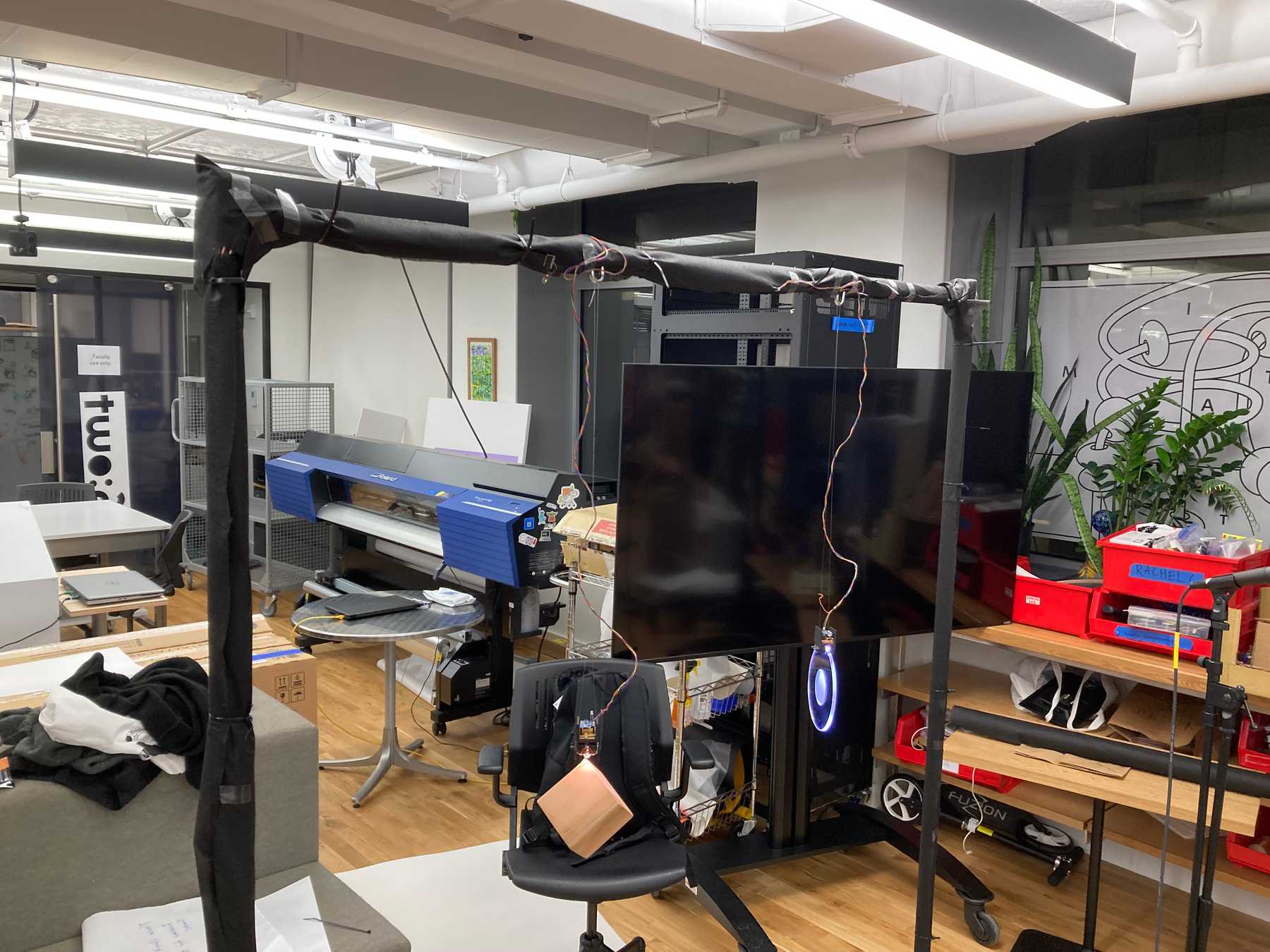
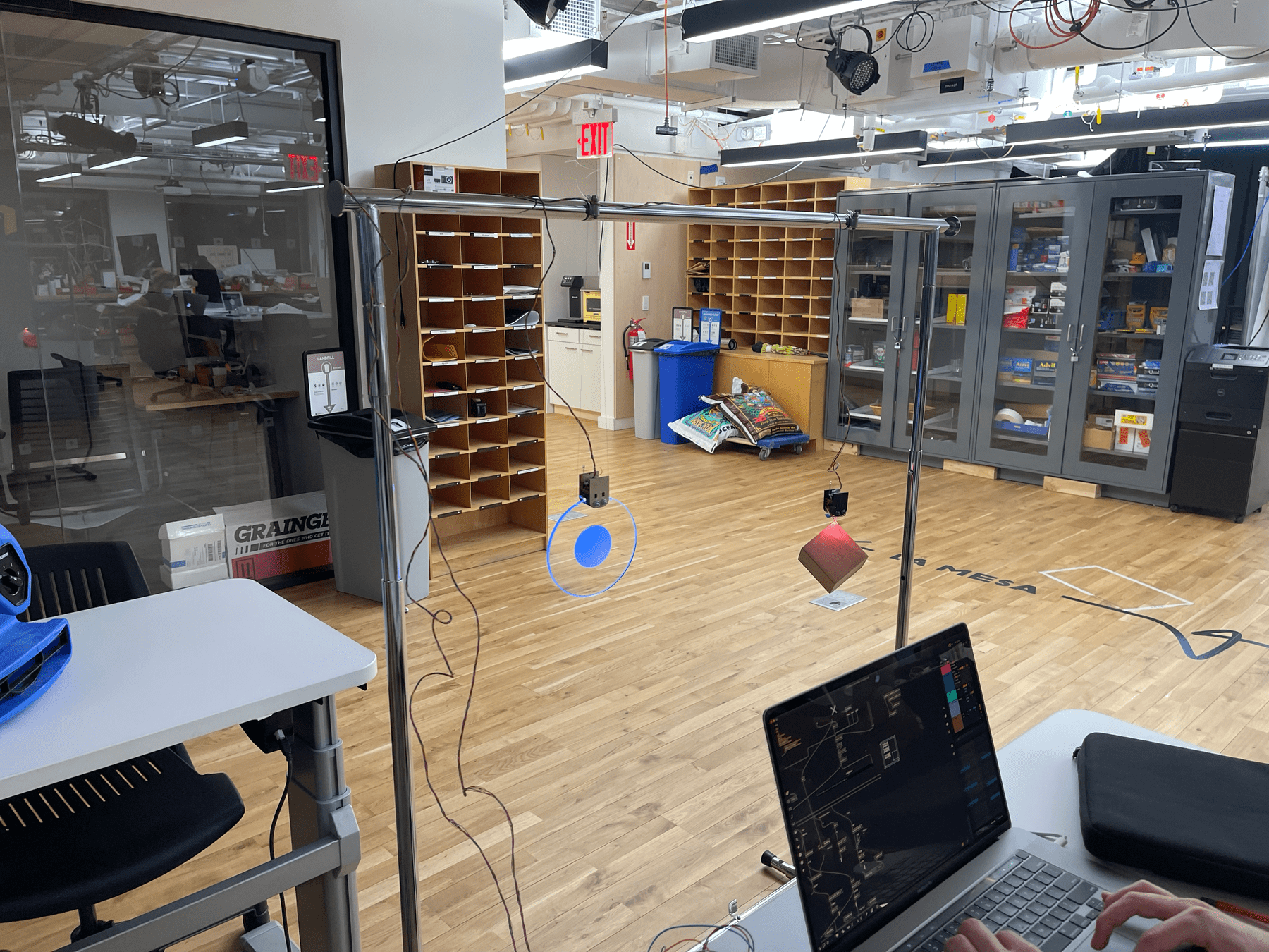 Testing both the cube and circle
Finishing Touches
For the final performance we mounted the objects on a large rack designed for holding a whiteboard. We covered the frame in black cloth and hid the wiring beneath.
Electronics
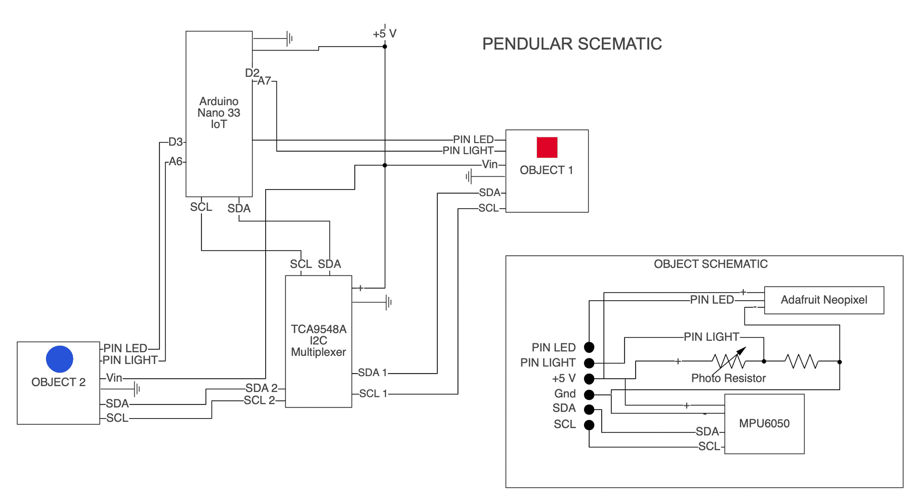
Each of our objects needed one accelerometer, one light sensor, and an LED. They connect to the central controller which connects to the computer.
We used an Arduino Nano 33 IoT, MPU6050 accelerometers and a TCA9548A I2C Multiplexer. The LEDs were short strips of an Adafruit NeoPixel LED strip.
Breadboard
The breadboard setup was straightforward. We just needed to connect the multiplexer to the arduino and the accelerometers.
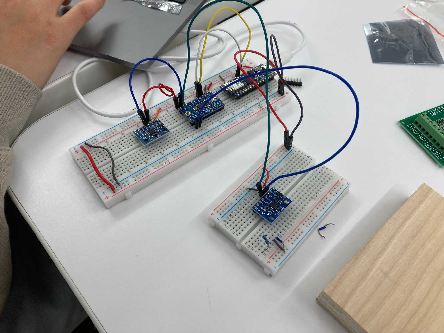 Initial setup with an arduino nano, and two MPU6050 accelerometers routed through a TCA9548A I2C Multiplexer
We initially tested the modules with an RJ45 cable connecting to the accelerometers.
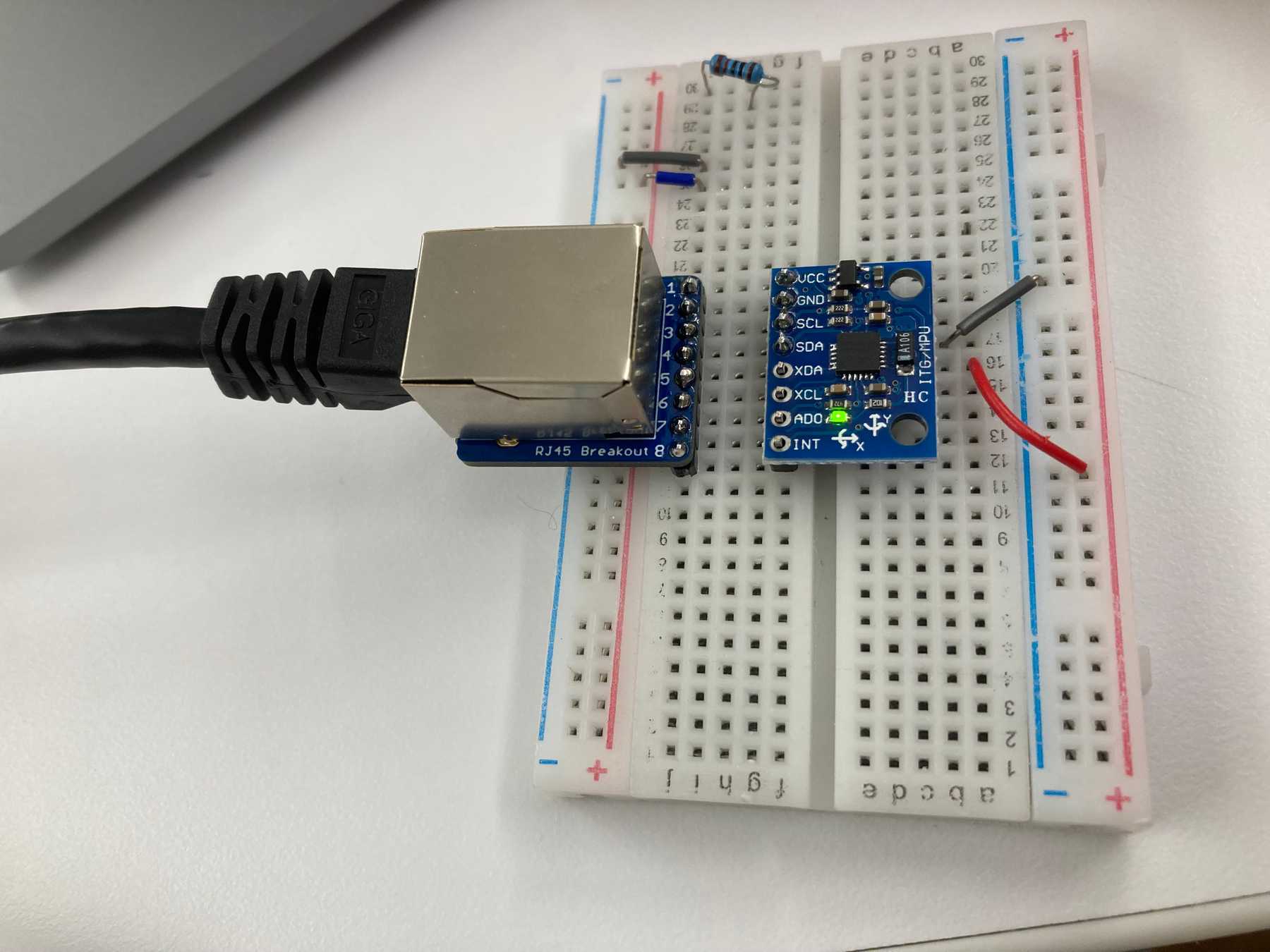 Moving the accelerometer to another breadboard
Handmade prototype
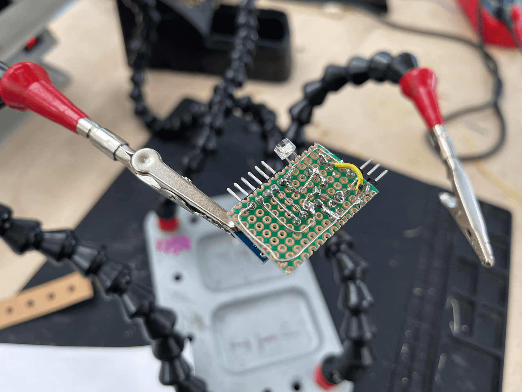
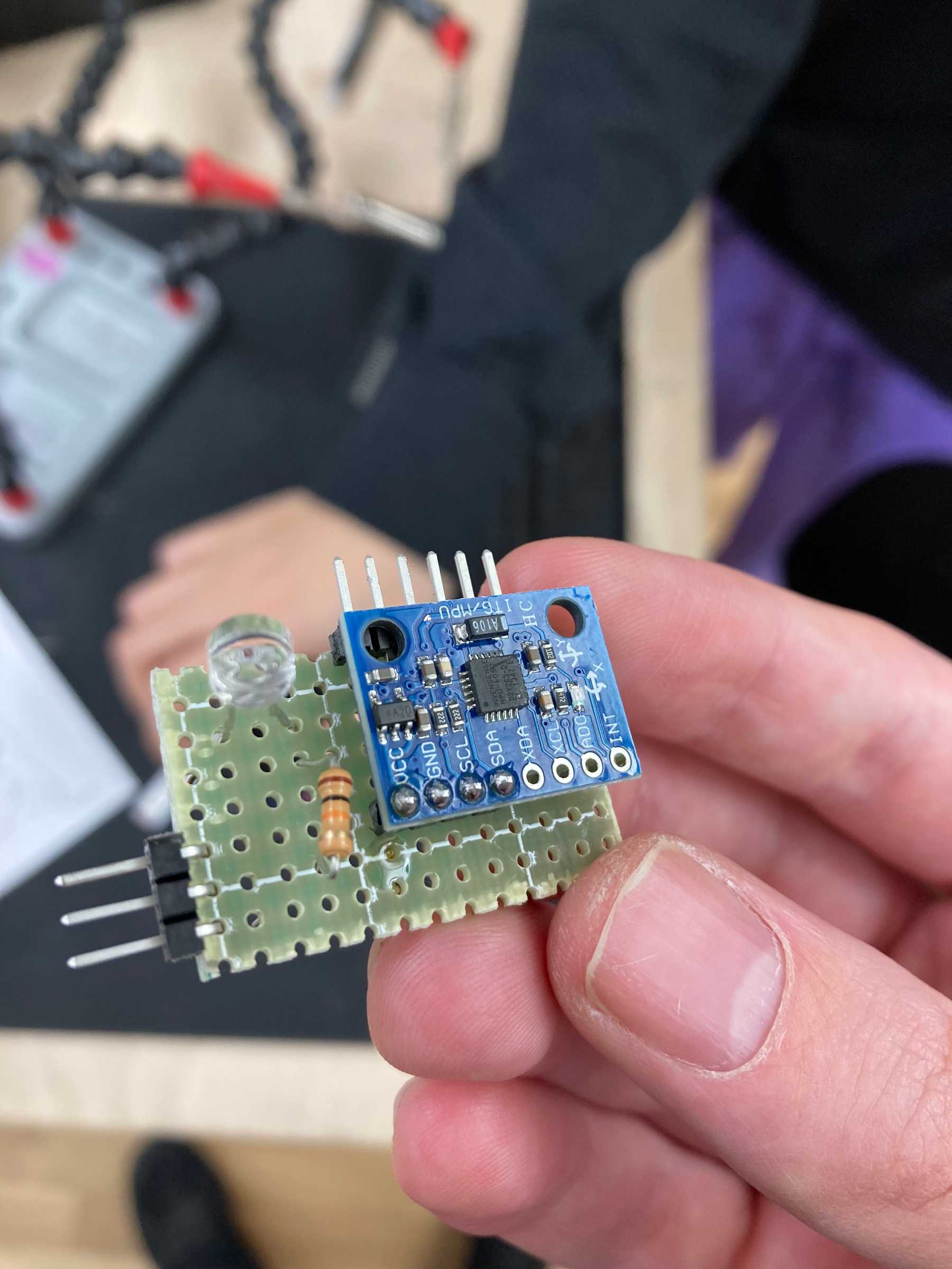
We needed the electronics on the objects to be as minimal as possible so we designed a circuit that we could fit in a small housing. For our first prototype we soldered the connections by hand.
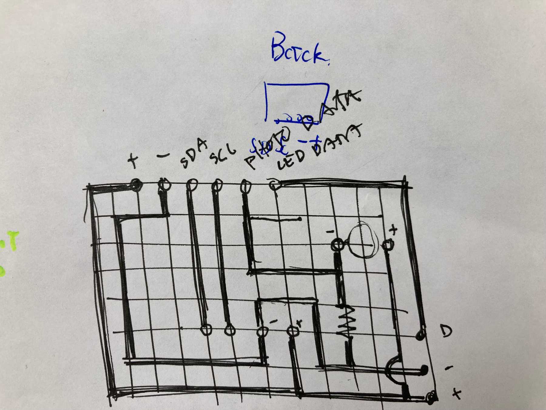 Initial circuit design for the hanging object
Each object needed 6 connections: power, ground, accelerometer SDA, accelerometer SCL, LED control data, and photo resistor data. The tricky part was avoiding crossed wires.
After a long time soldering we had the completed circuit working.
Milled PCB
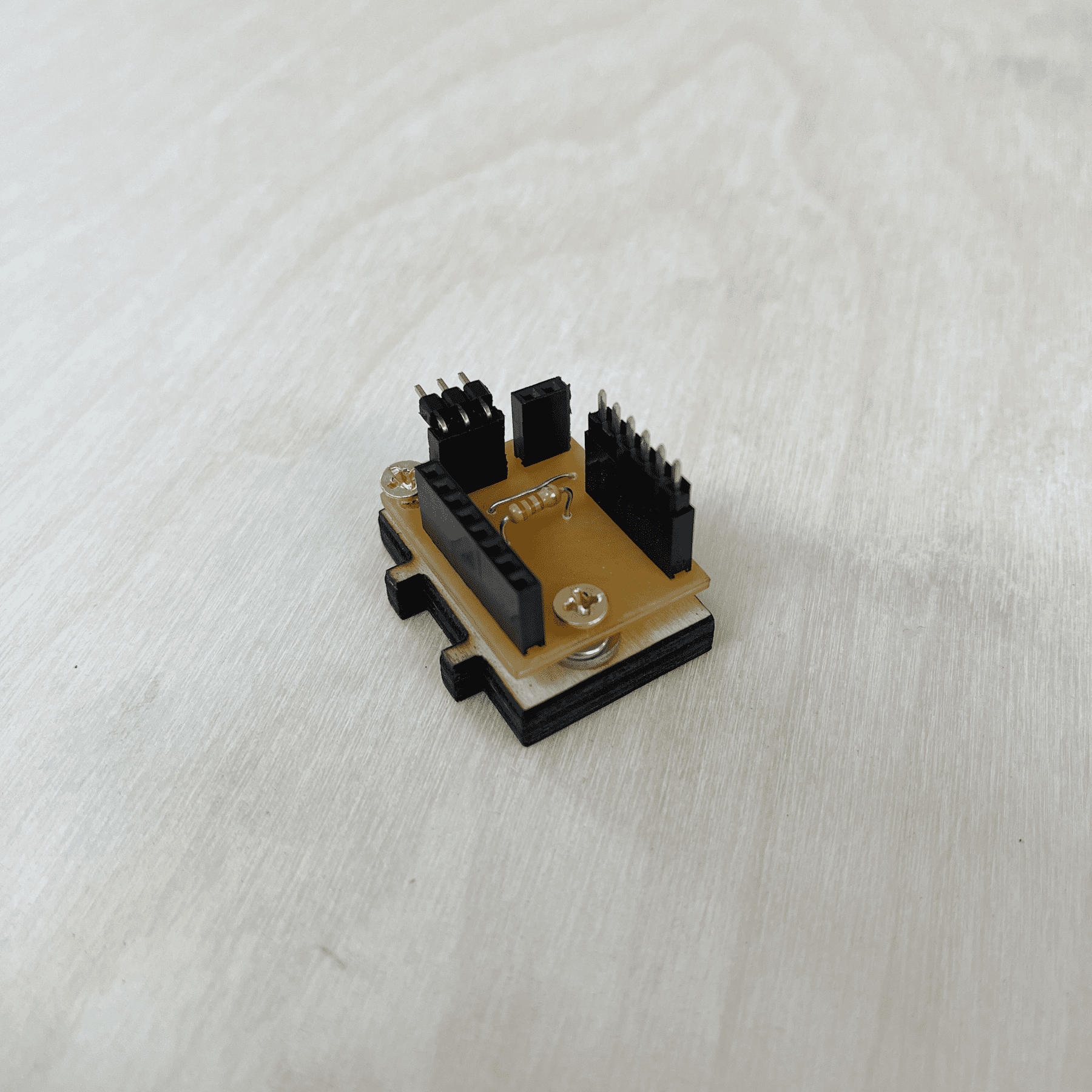
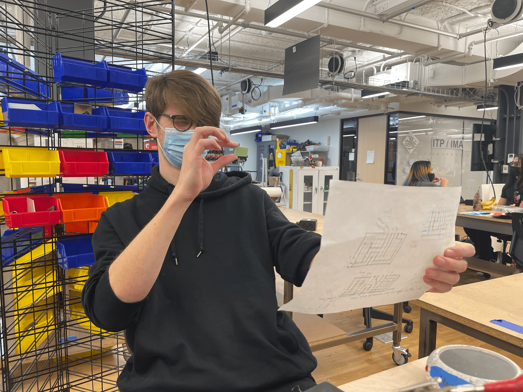
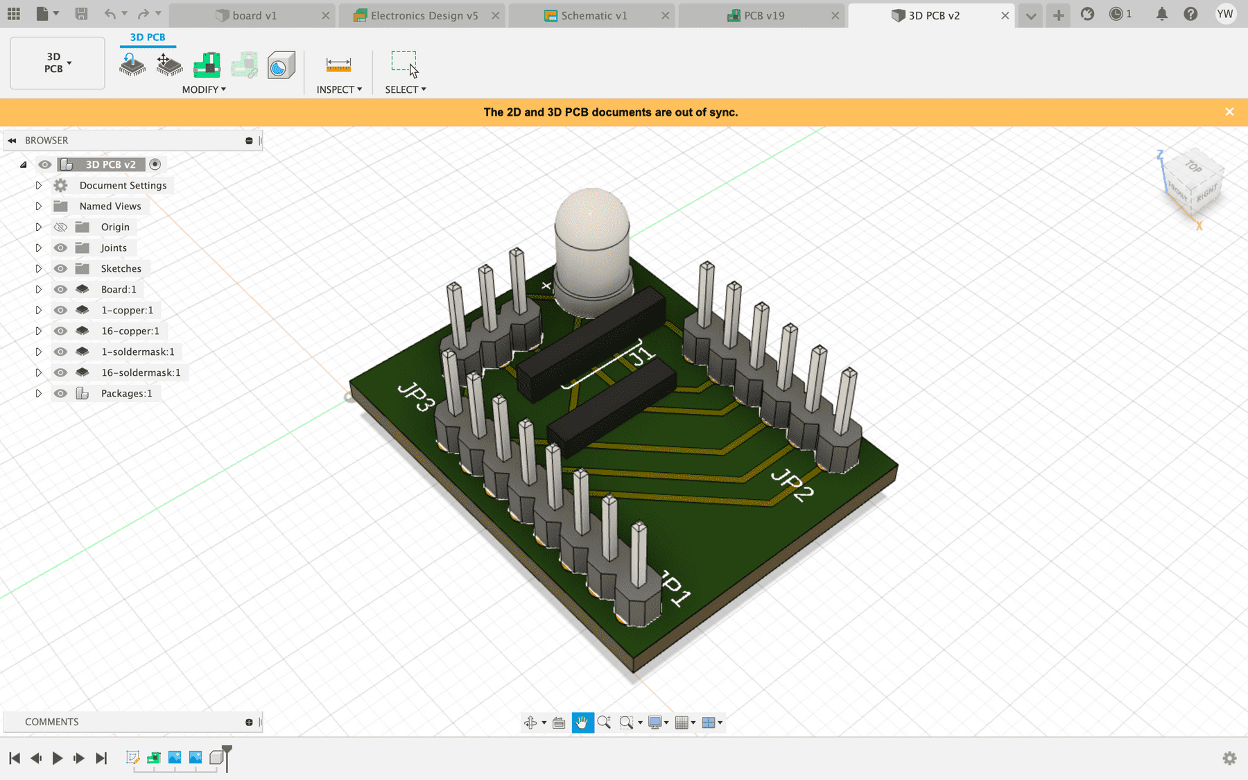
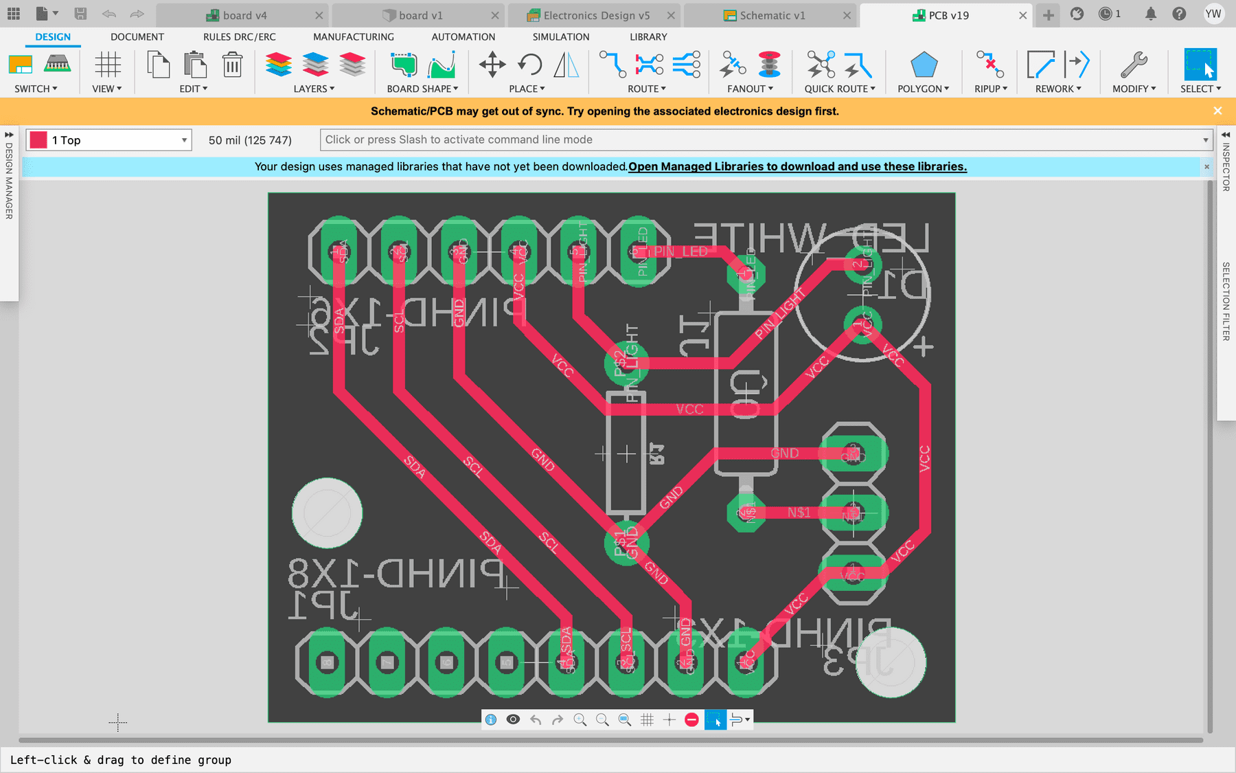
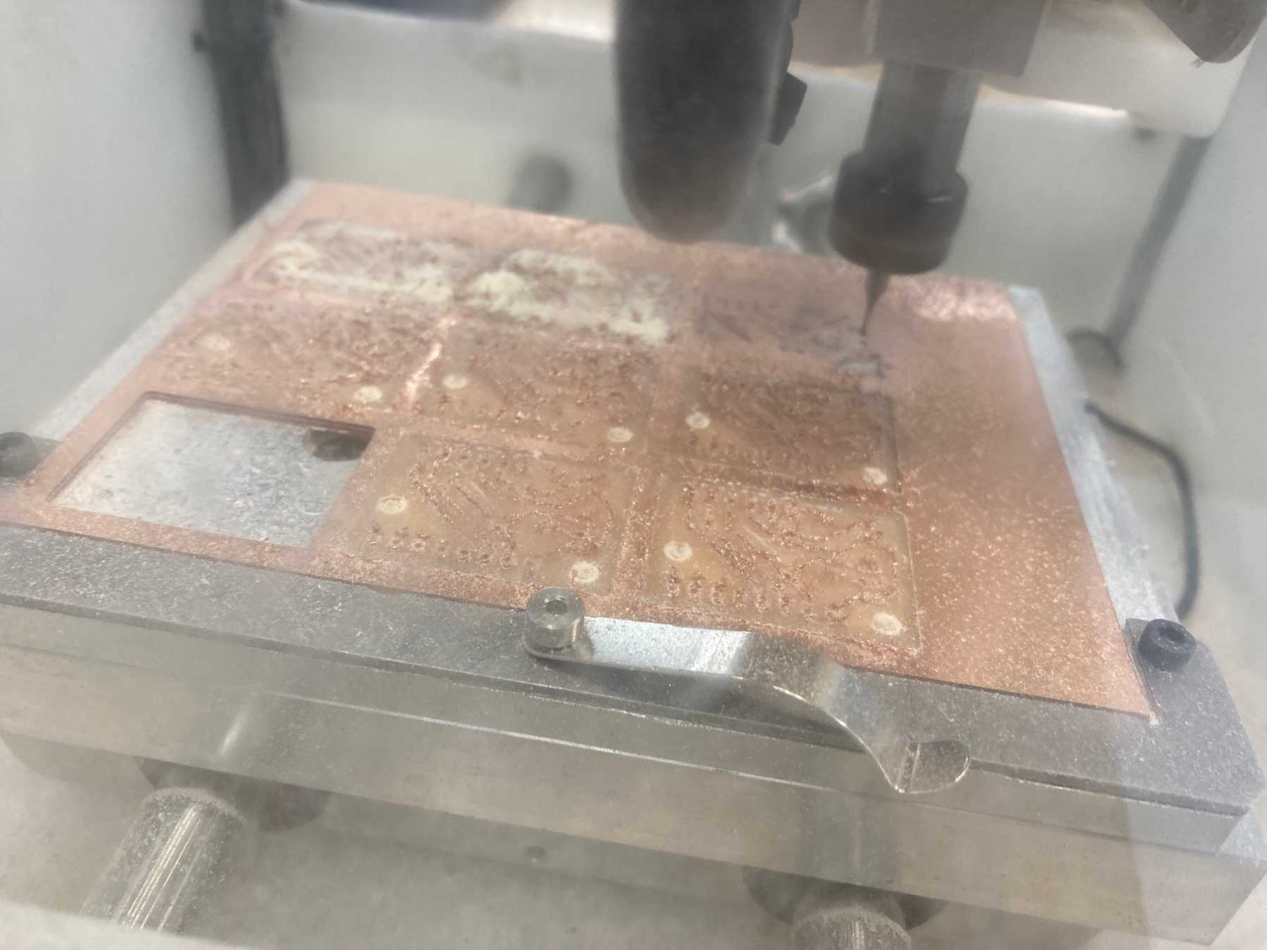
A HUGE thank you to Jason Gao who helped us design and mill custom PCBs for this project. After we finished the proof of concept we designed our custom PCB and milled it.
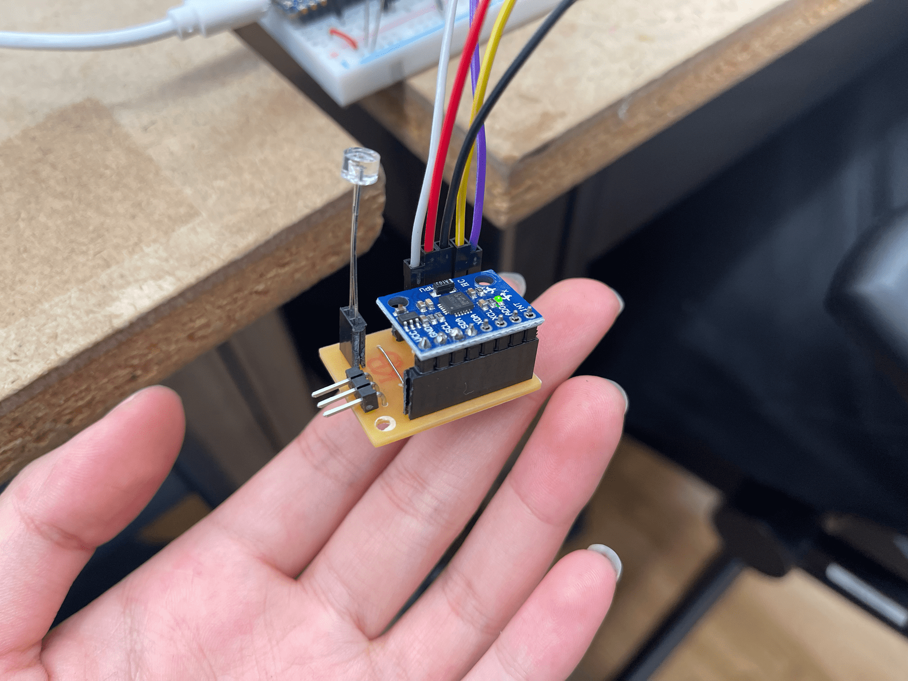 The new PCB with everything connected (except the light strip)
Code and Audio
The arduino code, max patch, and Ableton file are on GitHub.
Arduino Code
The arduino code reads the accelerometer and light sensor data and transmits it via Serial connection. It also accepts input over serial to control the brightness of the LEDs. We followed this tutorial on setting up the multiplexer to manage the two I2C devices. It uses the MPU6050_light and Adafruit NeoPixel libraries.
Max Patch
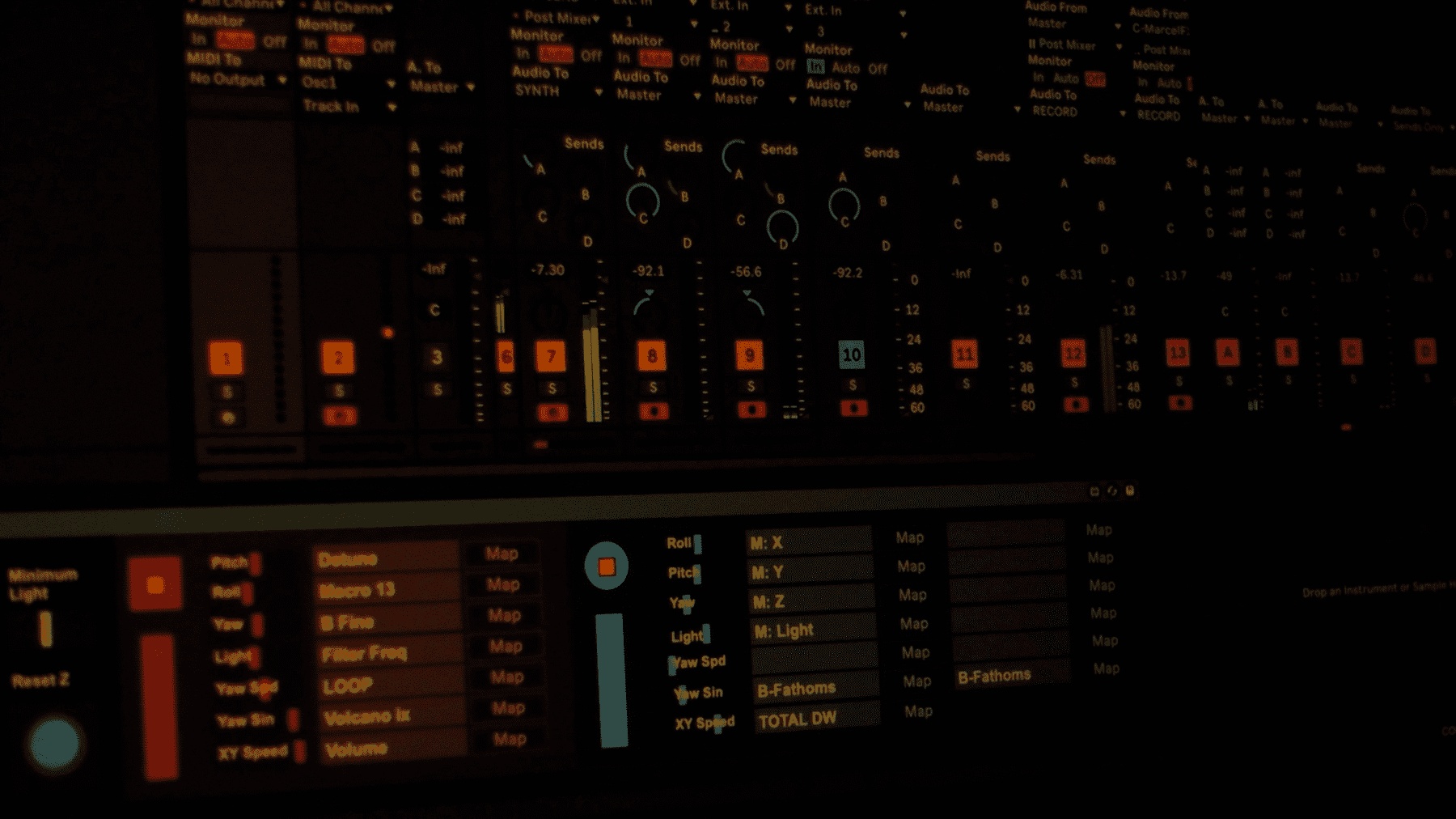
The Max patch reads the serial data and assigns the the values to certain parameters in Ableton. It also gives us live feedback on the state of the objects. We can map the different values by clicking “Map” and the selecting a parameter in Ableton.
Ableton File
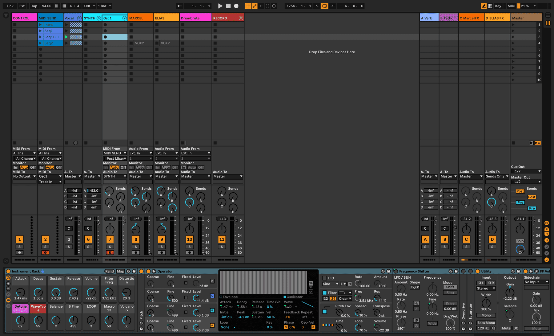 Screenshot of the Ableton File
We used Operator as the primary synth controlled by the cube. The swinging X/Y motion was mapped to a notch filter and a pitch bend. The spinning motion was mapped the the pitch of one oscillator set to a high harmonic, and the speed of the spinning was set to modulate how quickly another oscillator looped.
The circle controlled a chain of effects on the vocals — mostly delays and distortion to create a wind-like effect that was further modulated by the spinning motion.
