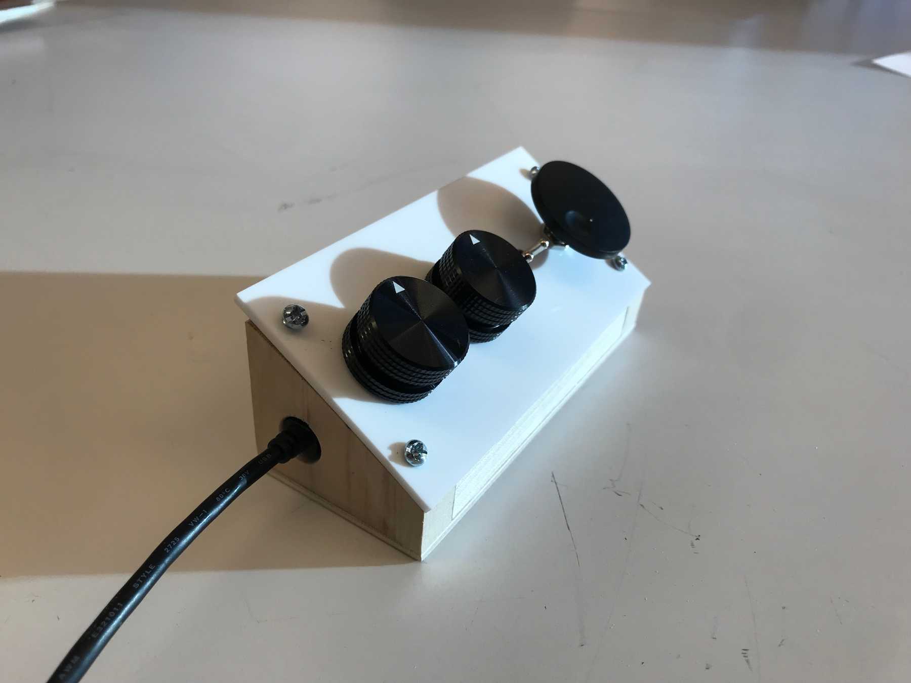
Enclosure: Ableton clip controller
April 21, 2021
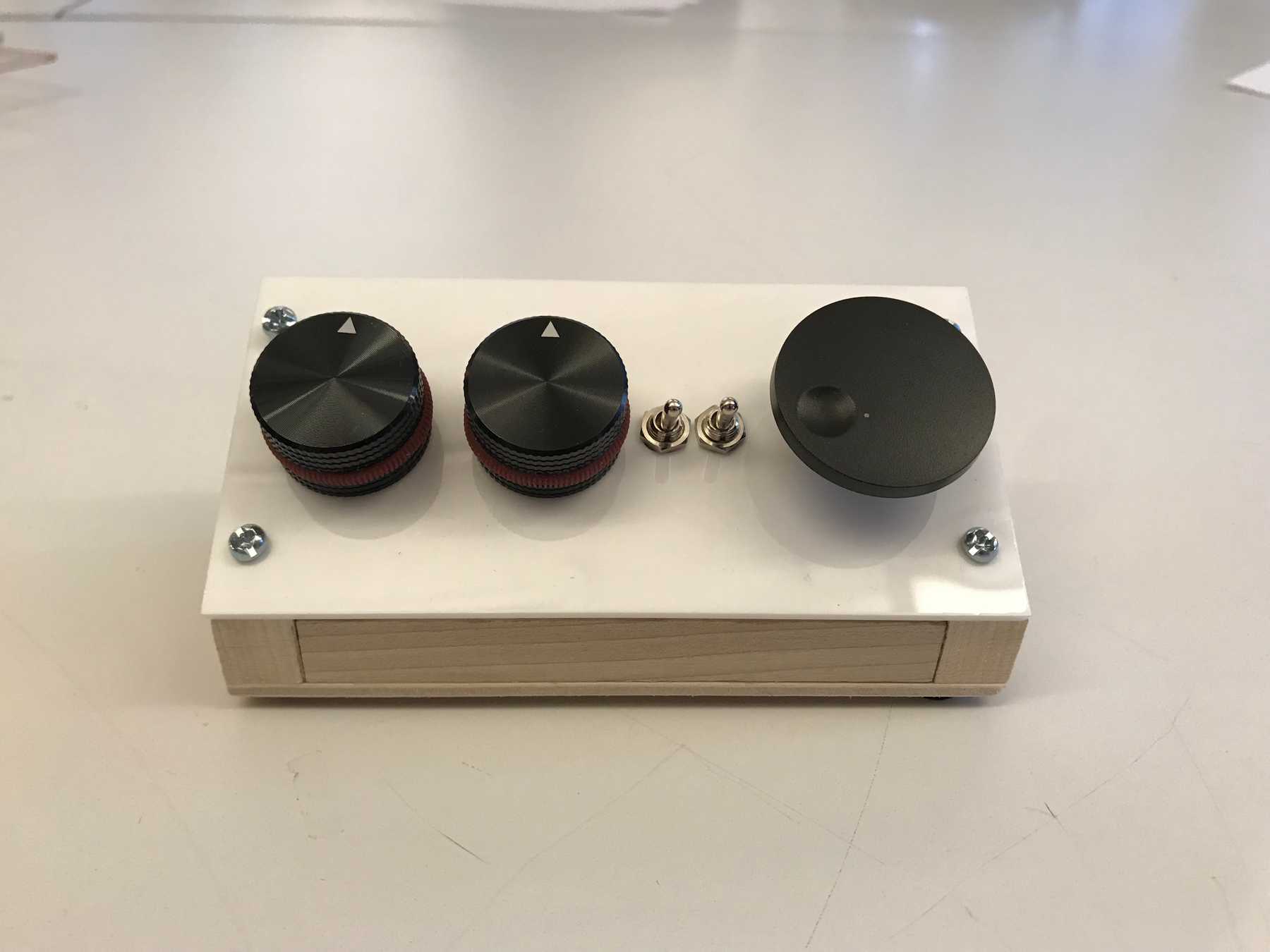
Intro to FabricationMy enclosure project is a small controller for Ableton Live that will allow me to adjust parameters without having to use the mouse or keyboard. I wanted three rotary encoders to control my three most used elements: clip gain, transposition, and start time for the currently selected clip. These are all difficult to control finely using the mouse especially when switching between multiple clips. I also wanted two toggle switches to control the granularity of the changes for the transposition and start time controls so that I could achieve coarse and fine adjustments.
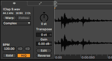 Screenshot of the Ableton clip control panel
Each rotary encoder also functions as a pushbutton. I’m thinking using the click to reset the value, but want to explore other options once I have everything wired up (there’s also potential for double click or hold). I bought all of the components from Adafruit.
Design
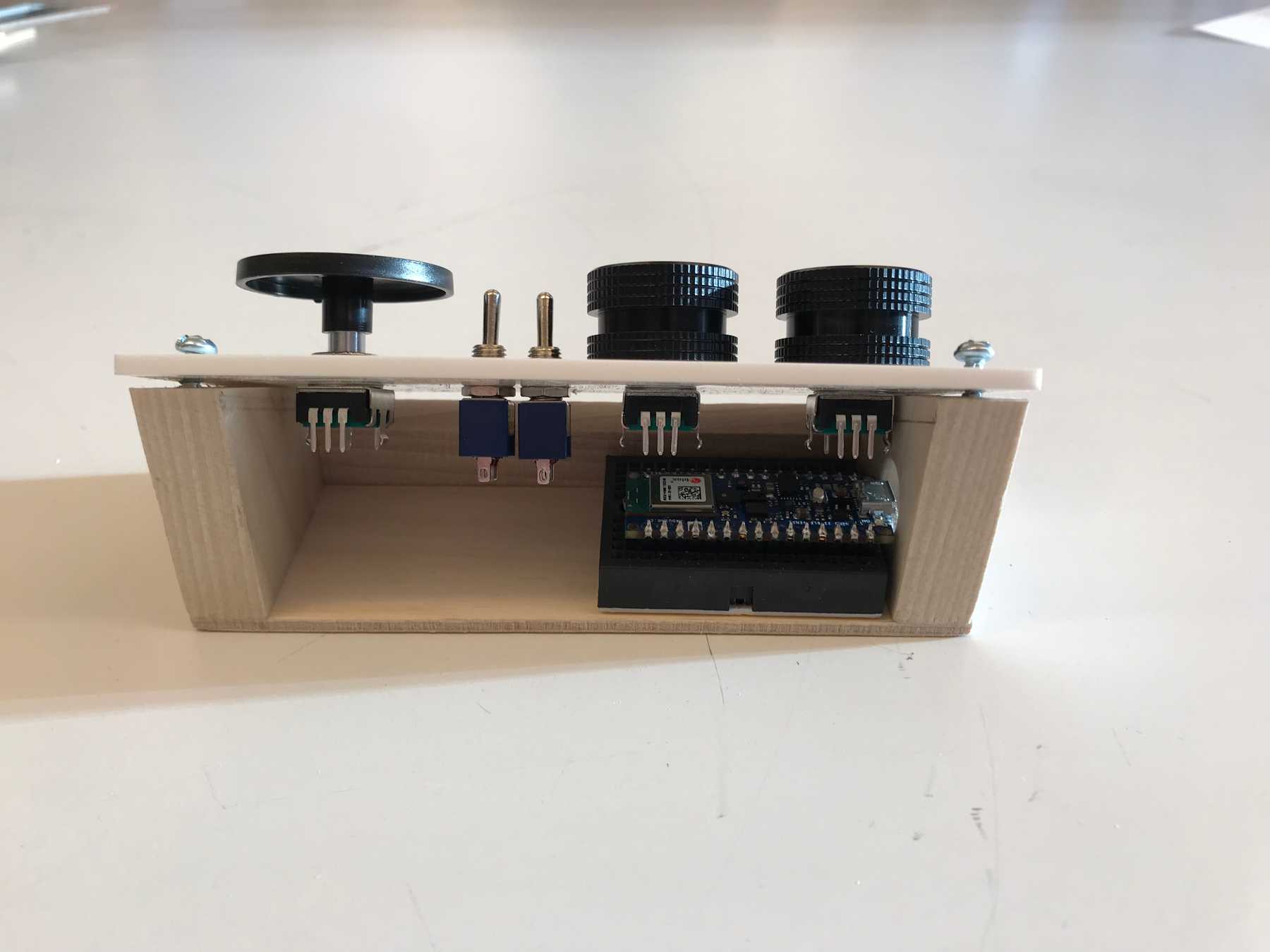
I designed the device in Illustrator trying to make sure there would be enough room for all of the components and Arduino with a tiny breadboard. The walls (1/2”), base(1/8”), and back(1/8”) would be wood and the top panel would be acrylic(1/8”). The back panel would be removable so I wanted the cable to come out of a hole drilled in the left wall. This also aligned nicely with how the Arduino would be placed.
 The schematic in Illustrator. The red areas show the Arduino and breadboard position
I wasn’t able to implement this yet but I wanted the back panel to attach by friction using dowel connectors drilled into the side walls so that it would be easily removable.
Making the Box
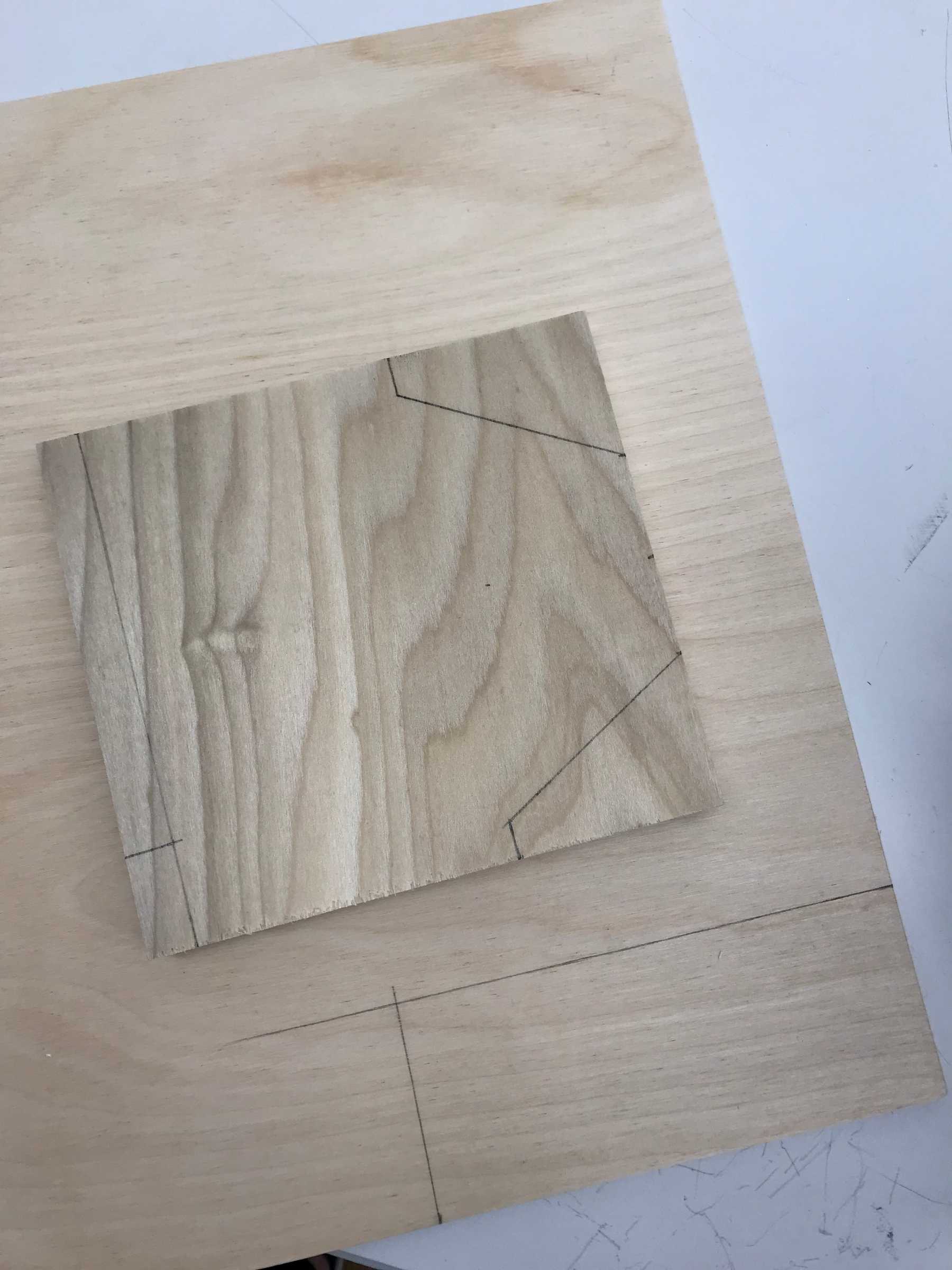
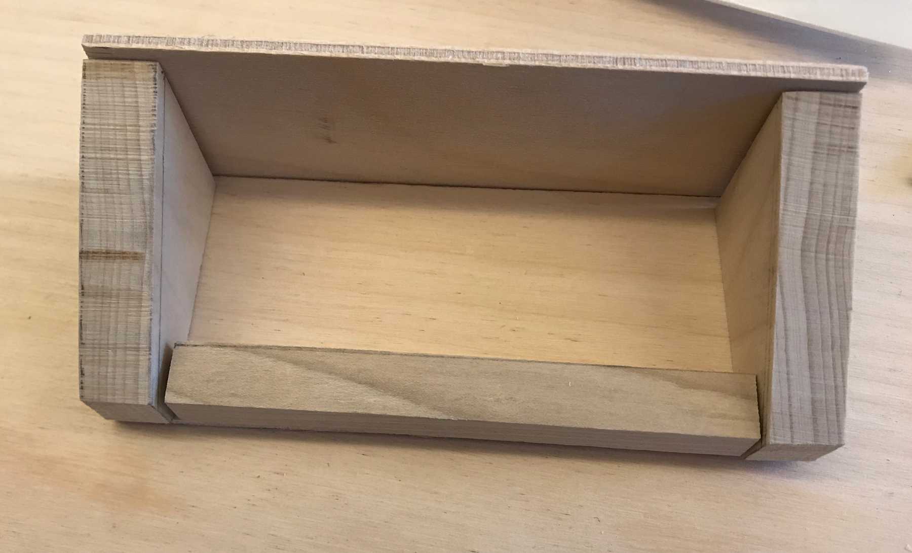
I started with the wooden box, using the band saw to cut the walls out of poplar, and base and back out of birch.
I left the back panel a bit bigger so that I could sand it to fit flush with the acrylic panel.
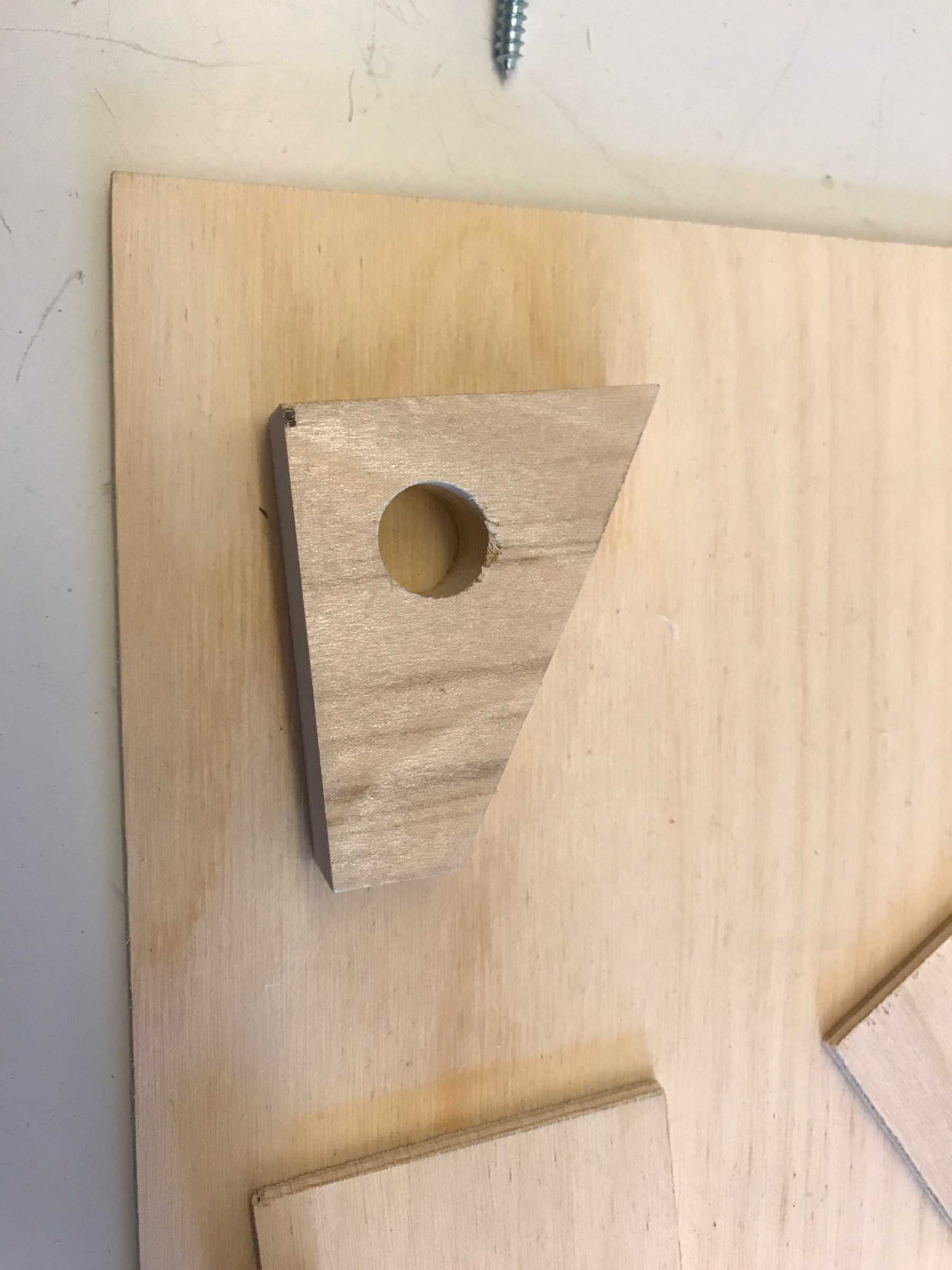
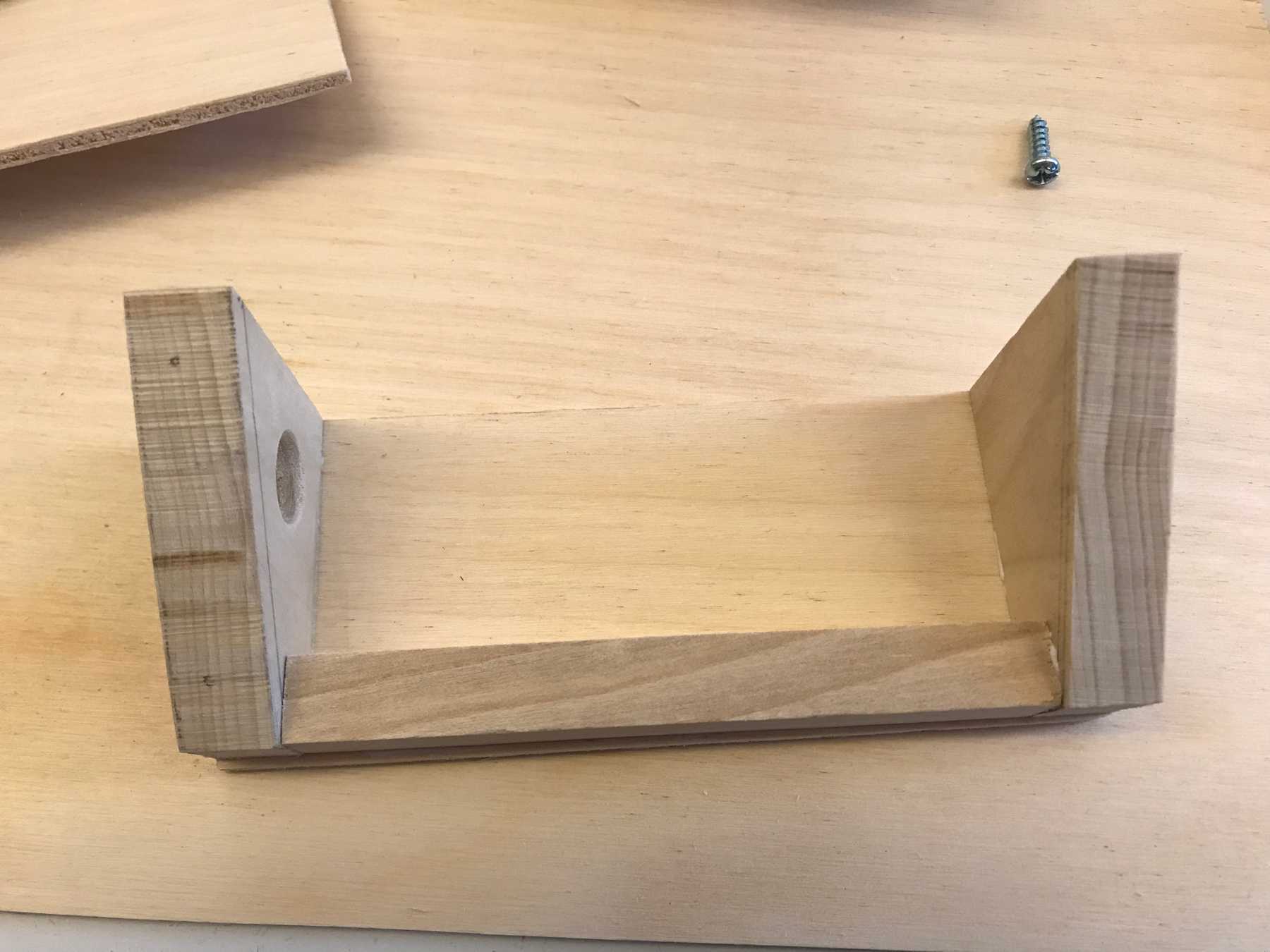
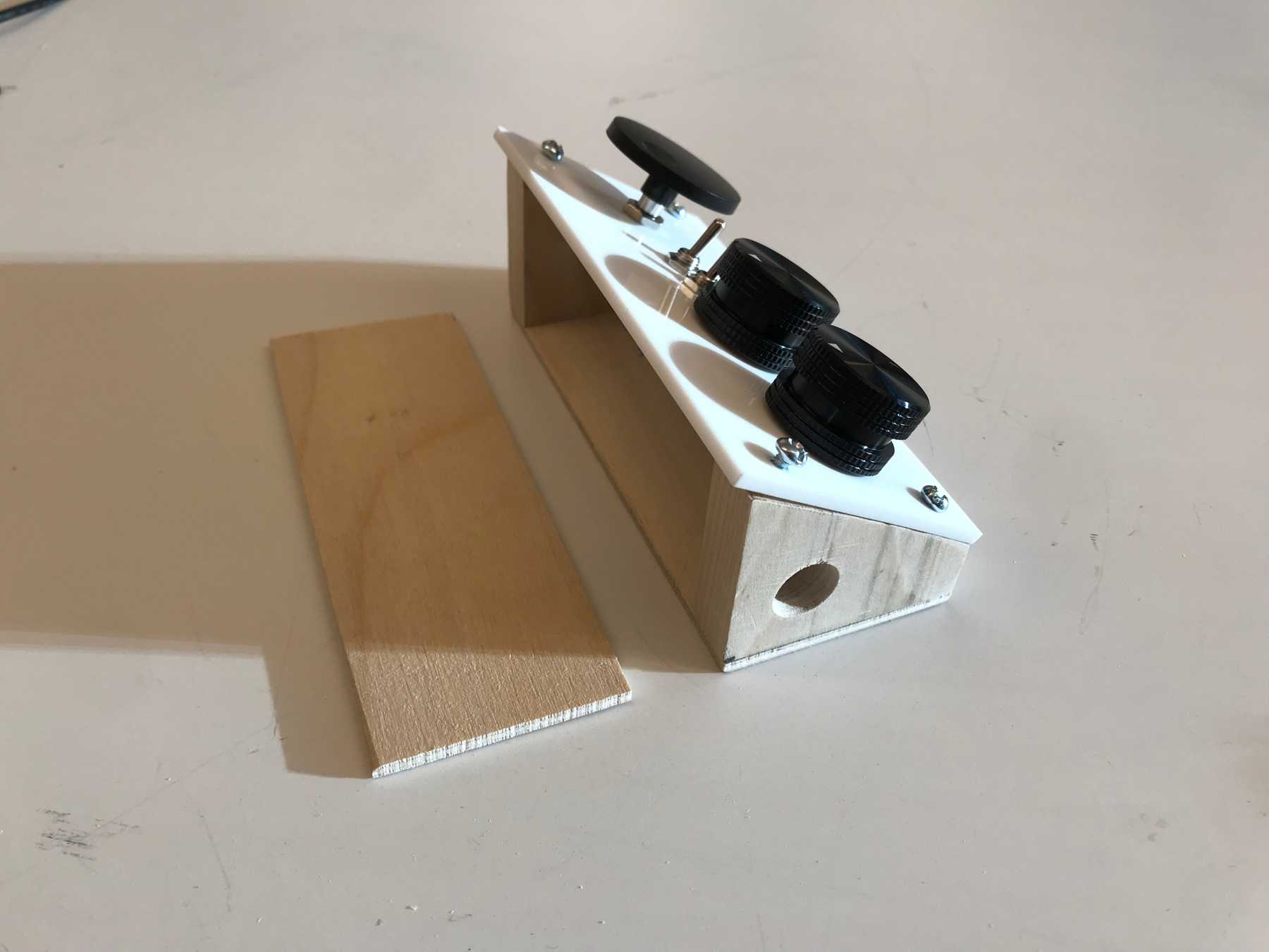
The last step before assembly was to drill the cable hole. I measured the bit to fit the cable and drilled with the drill press.
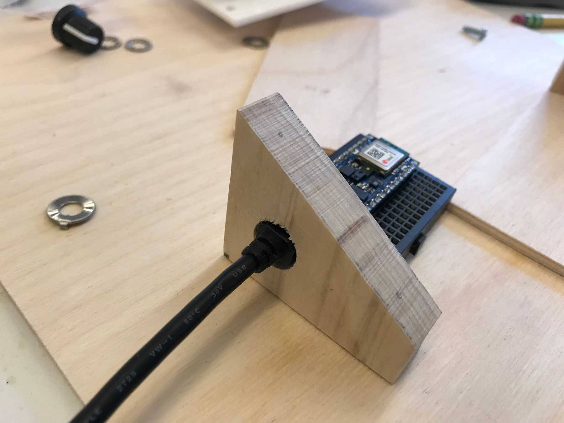 Plugging in the Arduino through the hole
After I took this picture I sanded the inside of the hole so that it was smooth. I then glued the pieces together with wood glue. I had initially planned to nail them but was short on time. Since it’s such a small box I felt ok with glue — anything bigger and I would have wanted to nail it to make it feel more solid.
The Faceplate
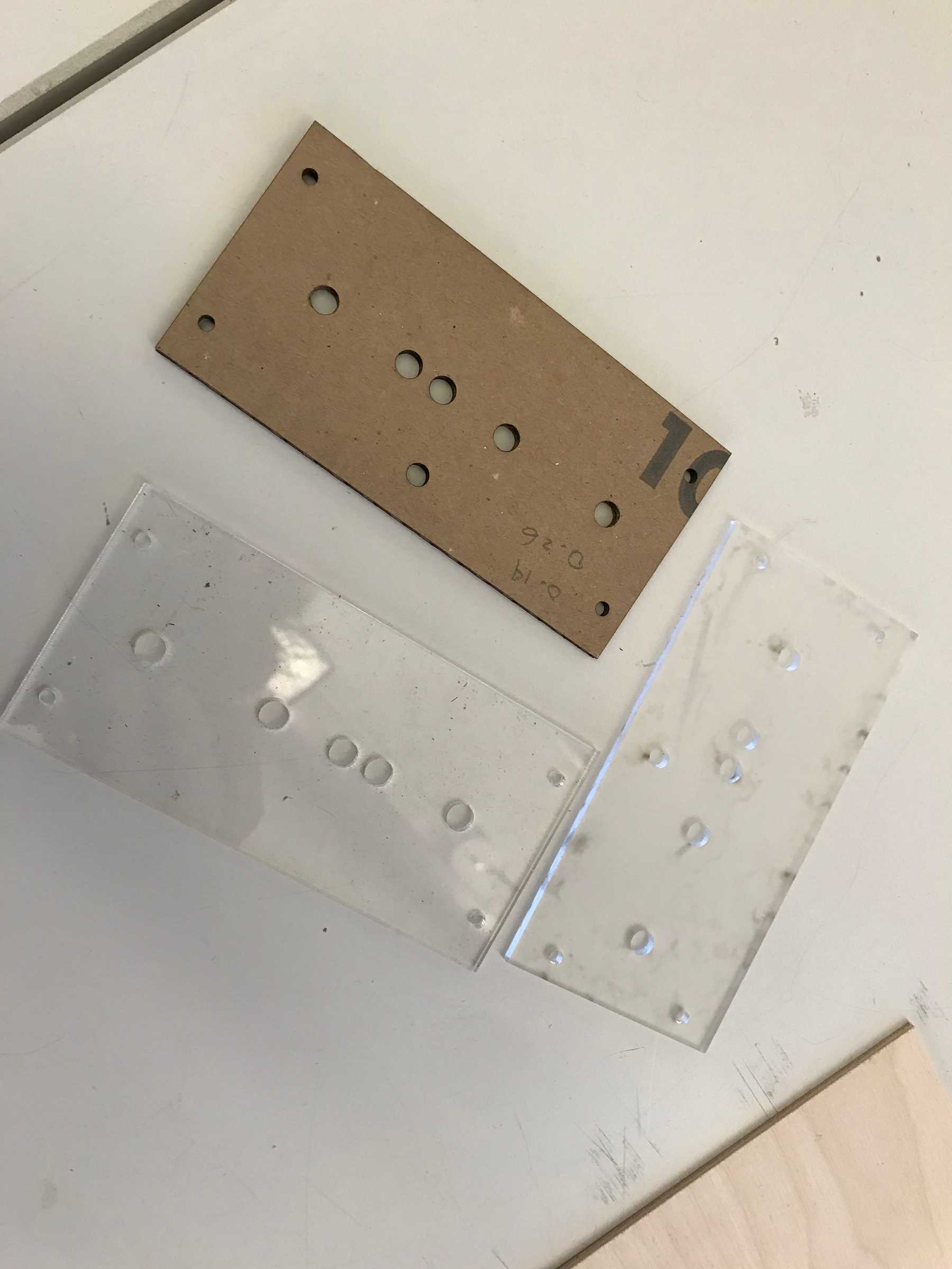
I laser cut the faceplate out of acrylic. It took several tests to find the right width for the component and drill holes.
I attached the components to the panel to make sure they fit properly and could be wired within the space provided by the box.
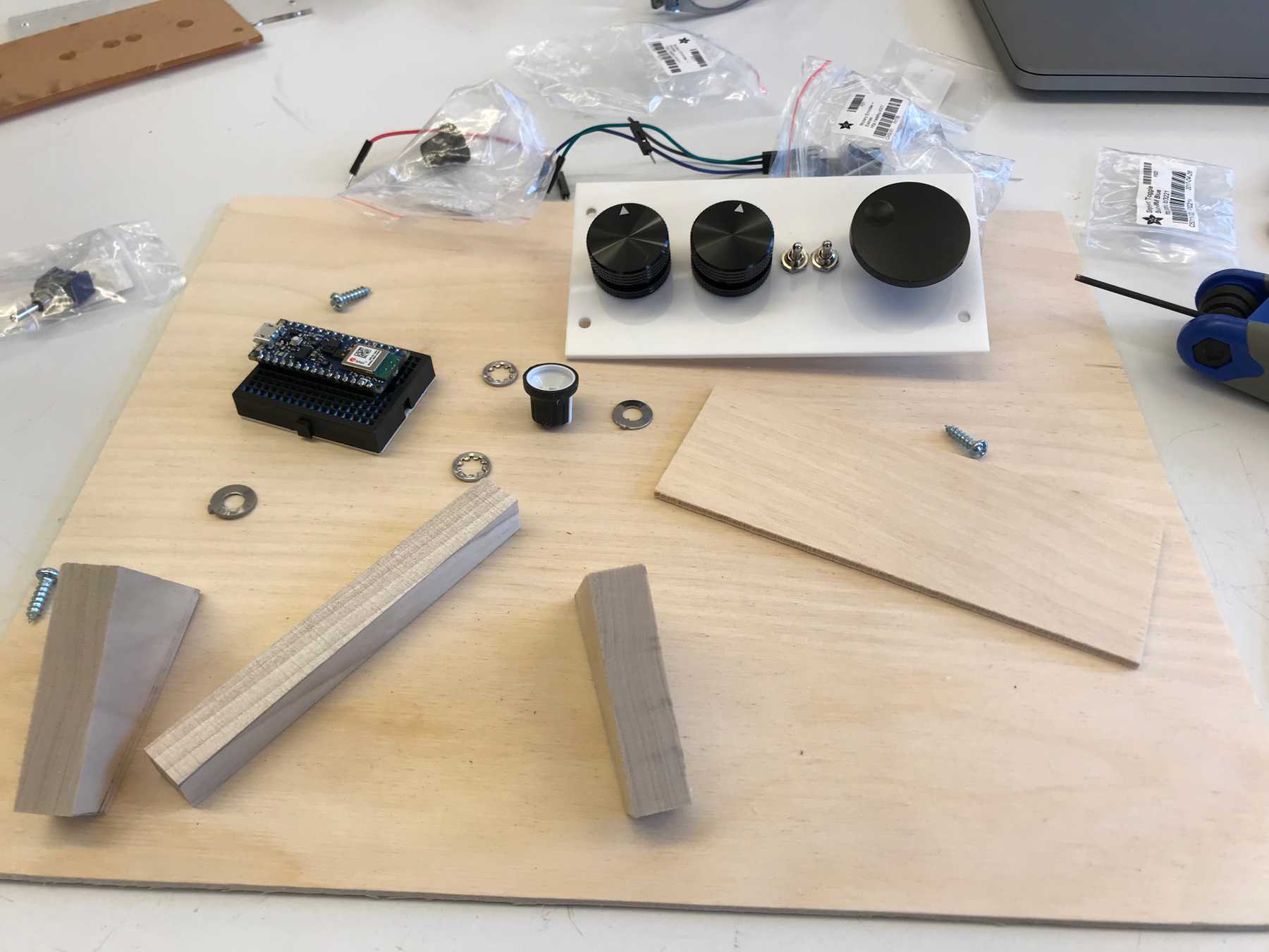 Attaching the components to the panel
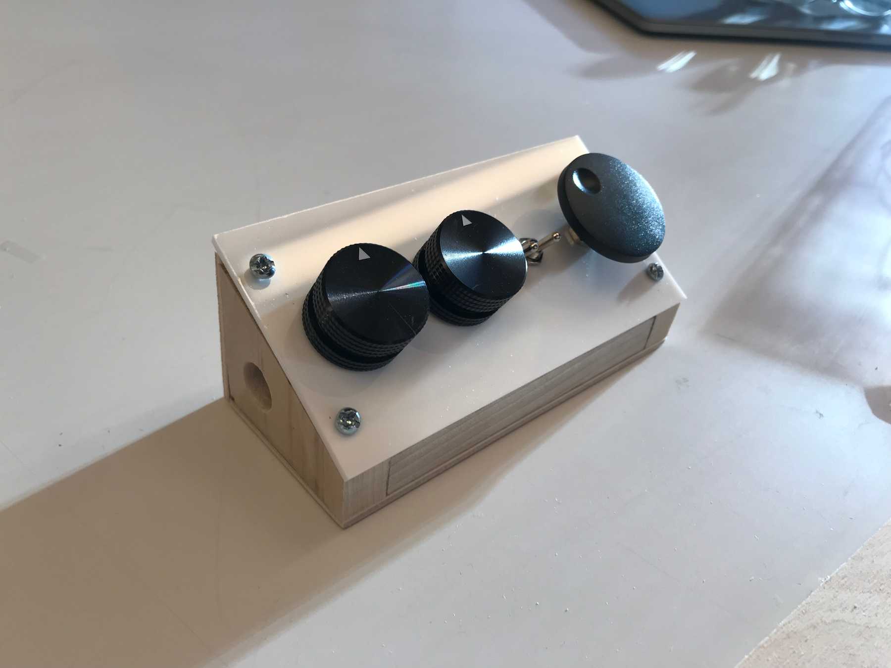
It was finally time to screw on the faceplate. Using the holes in the acrylic as guides I drilled pilot holes in the walls and then small round-headed screws. This was the most imprecise part of the process and I think I should have used the drill jig to make sure the pilot holes were square to the edge. However the holes were not exactly in the center of the edge which is why I waited until this step to drill. In the end it came out ok even though one of the screws was a little crooked.
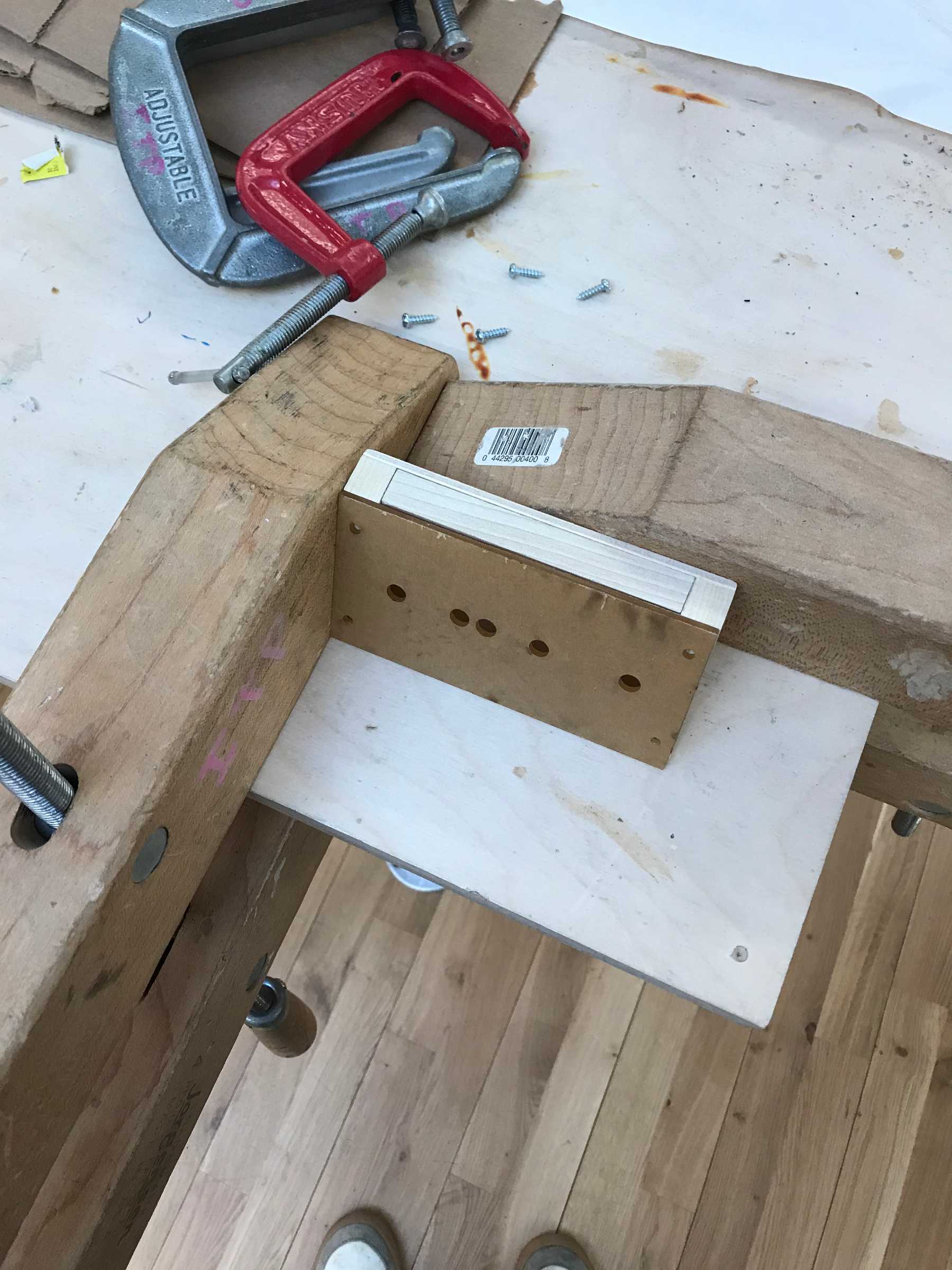 Securing the box to drill the panel on
The Result
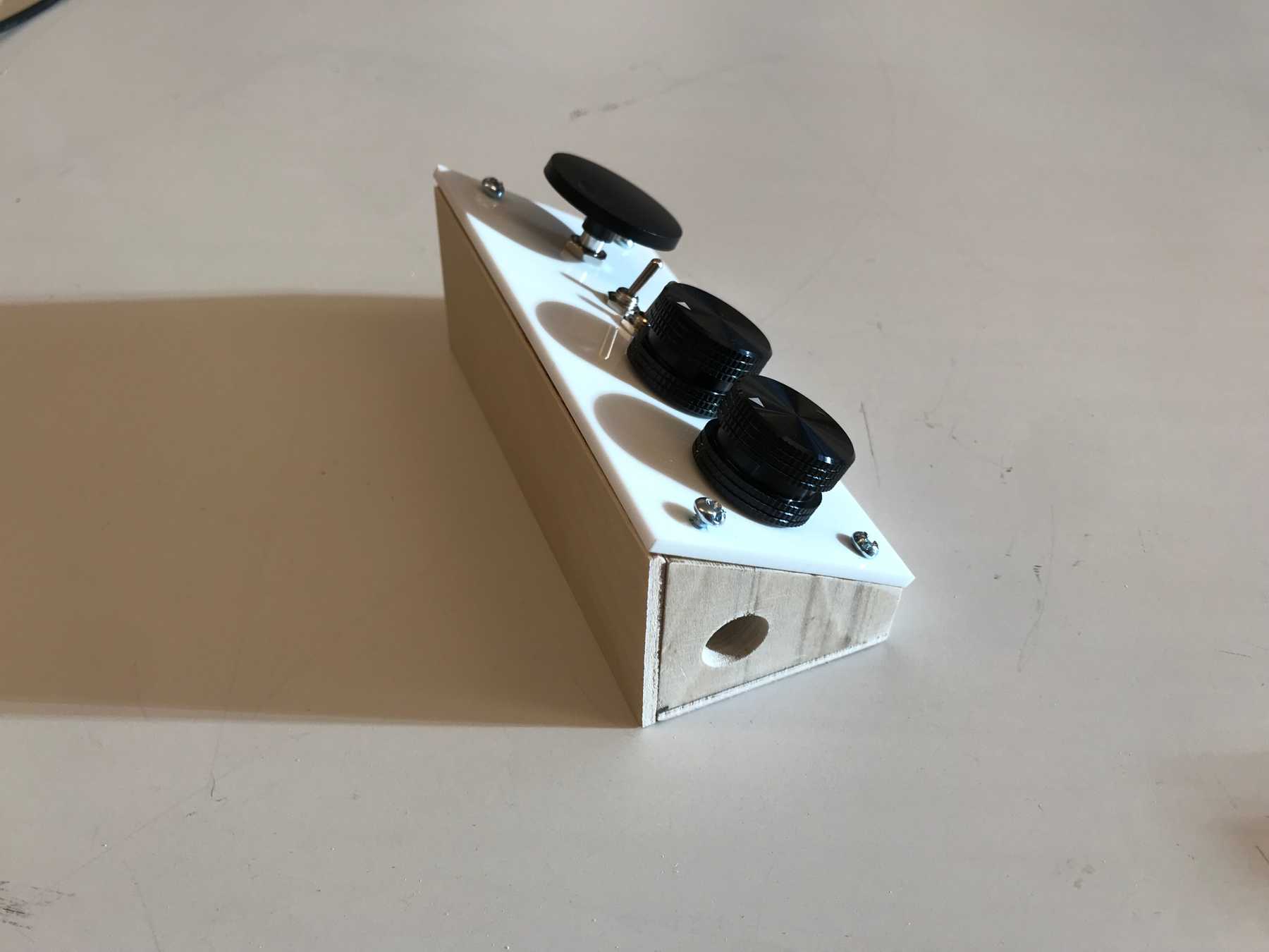
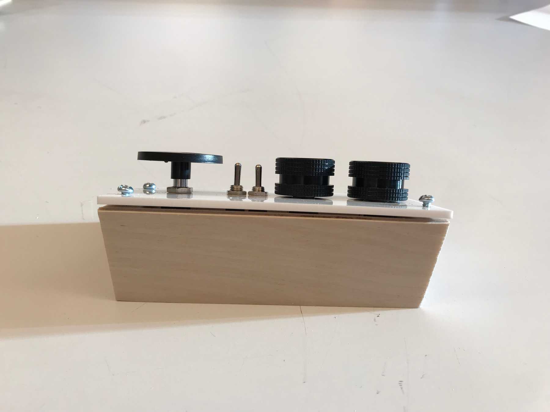
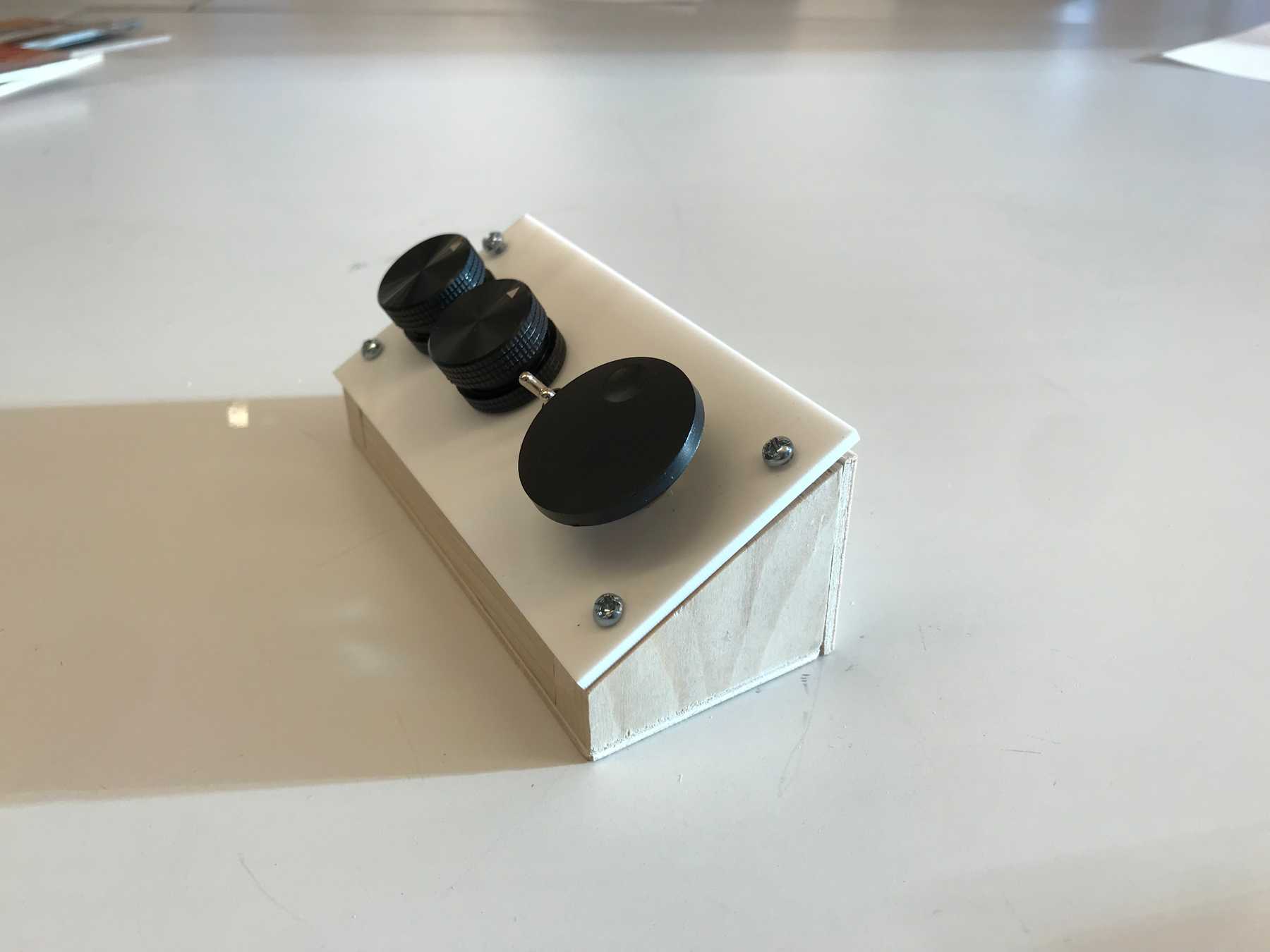
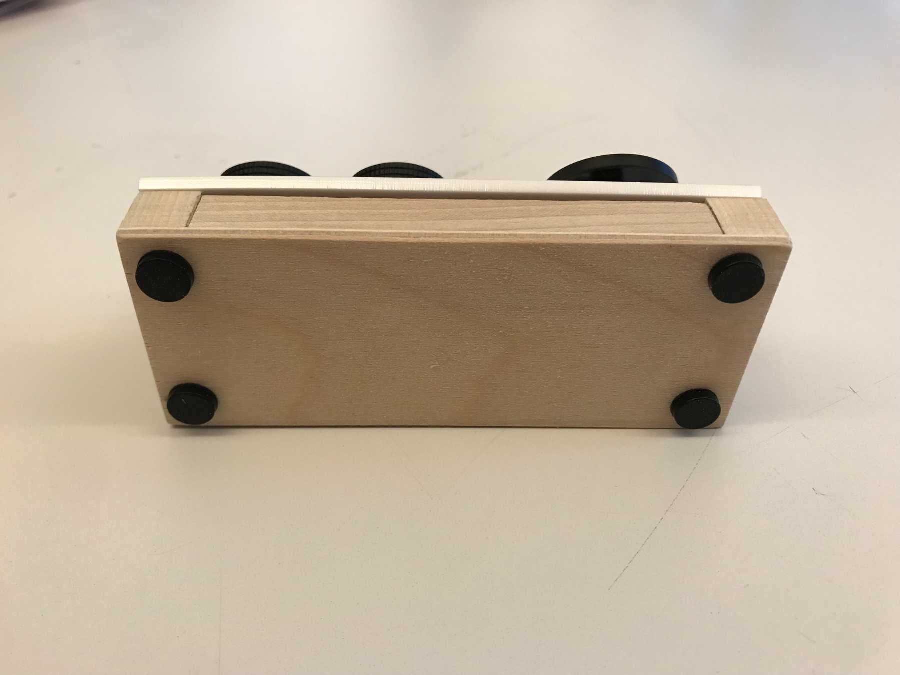
The result feels pretty solid and reflects the initial design well. The one part I did not get to finish was the removable back panel. I think I can secure it with push pins for now but hope to use dowel pegs for a more finished solution. For the final touch I added rubber feet to the bottom.
